ÐаÑалог Weidmuller: Electronics - Analogue Signal Conditioning
ÐаÑалог Weidmuller: Electronics - Analogue Signal Conditioning
ÐаÑалог Weidmuller: Electronics - Analogue Signal Conditioning

Create successful ePaper yourself
Turn your PDF publications into a flip-book with our unique Google optimized e-Paper software.
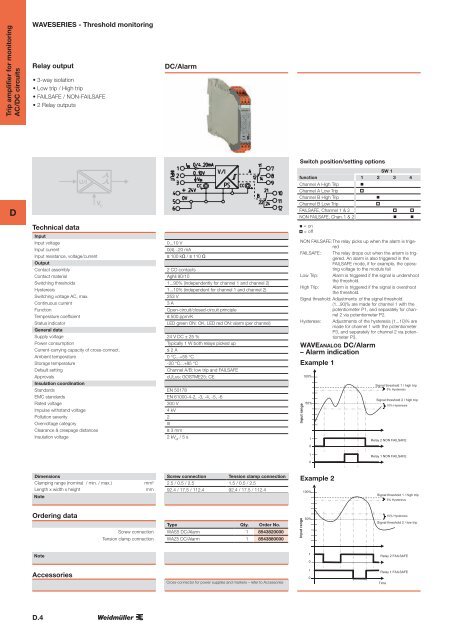
Trip amplifier for monitoring<br />
AC/DC circuits<br />
WAVESERIES - Threshold monitoring<br />
Relay output<br />
• 3-way isolation<br />
• Low trip / High trip<br />
• FAILSAFE / NON-FAILSAFE<br />
• 2 Relay outputs<br />
DC/Alarm<br />
Switch position/setting options<br />
D<br />
U/I<br />
V C<br />
SW 1<br />
function 1 2 3 4<br />
Channel A High Trip <br />
Channel A Low Trip <br />
Channel B High Trip<br />
<br />
Channel B Low Trip<br />
<br />
FAILSAFE, Channel 1 & 2 <br />
NON FAILSAFE, Chan. 1 & 2 <br />
Technical data<br />
Input<br />
Input voltage<br />
Input current<br />
Input resistance, voltage/current<br />
Output<br />
Contact assembly<br />
Contact material<br />
Switching thresholds<br />
Hysteresis<br />
Switching voltage AC, max.<br />
Continuous current<br />
Function<br />
Temperature coefficient<br />
Status indicator<br />
General data<br />
Supply voltage<br />
Power consumption<br />
Current-carrying capacity of cross-connect.<br />
Ambient temperature<br />
Storage temperature<br />
Default setting<br />
Approvals<br />
Insulation coordination<br />
Standards<br />
EMC standards<br />
Rated voltage<br />
Impulse withstand voltage<br />
Pollution severity<br />
Overvoltage category<br />
Clearance & creepage distances<br />
Insulation voltage<br />
0...10 V<br />
0(4)...20 mA<br />
≥ 100 kΩ / ≤ 110 Ω<br />
2 CO contacts<br />
AgNi 90/10<br />
1...90% (independently for channel 1 and channel 2)<br />
1...10% (independent for channel 1 and channel 2)<br />
253 V<br />
3 A<br />
Open-circuit/closed-circuit principle<br />
≤ 500 ppm/K<br />
LED green ON: OK, LED red ON: alarm (per channel)<br />
24 V DC ± 25 %<br />
Typically 1 W both relays picked up<br />
≤ 2 A<br />
0 °C...+55 °C<br />
-20 °C...+85 °C<br />
Channel A/B: low trip and FAILSAFE<br />
cULus; GOSTME25; CE<br />
EN 50178<br />
EN 61000-4-2, -3, -4, -5, -6<br />
300 V<br />
4 kV<br />
2<br />
III<br />
≥ 3 mm<br />
2 kV eff<br />
/ 5 s<br />
= on<br />
= off<br />
NON FAILSAFE:The relay picks up when the alarm is trigered<br />
FAILSAFE: The relay drops out when the arlarm is triggered.<br />
An alarm is also triggered in the<br />
FAILSAFE mode, if for example, the operating<br />
voltage to the moduls fail<br />
Low Trip: Alarm is triggered if the signal is undershoot<br />
the threshold.<br />
High Trip: Alarm is triggered if the signal is overshoot<br />
the threshold.<br />
<strong>Signal</strong> threshold: Adjustments of the signal threshold<br />
(1...90)% are made for channel 1 with the<br />
potentiometer P1, and separately for channel<br />
2 via potentiometer P2.<br />
Hysterese: Adjustments of the hysteresis (1...10)% are<br />
made for channel 1 with the potentiometer<br />
P3, and separately for channel 2 via potentiometer<br />
P3.<br />
WAVEANALOG DC/Alarm<br />
– Alarm indication<br />
Example 1<br />
Input range<br />
100%<br />
50%<br />
1<br />
Sc al <strong>Signal</strong> threshold ll 2 / high 1 / trip high trip<br />
5% Hysteresis<br />
Schal<strong>Signal</strong> chwelle threshold 1 / high 2 trip / high trip<br />
10% Hysteresis<br />
Relay 2 NON FAILSAFE<br />
0<br />
1<br />
Relay 1 NON FAILSAFE<br />
0<br />
Zeit<br />
Dimensions<br />
Clamping range (nominal / min. / max.)<br />
Length x width x height<br />
Note<br />
mm²<br />
mm<br />
Screw connection Tension clamp connection<br />
2.5 / 0.5 / 2.5 1.5 / 0.5 / 2.5<br />
92.4 / 17.5 / 112.4 92.4 / 17.5 / 112.4<br />
Example 2<br />
100%<br />
<strong>Signal</strong> threshold 1 / high trip<br />
5% Hysteresis<br />
Ordering data<br />
Screw connection<br />
Tension clamp connection<br />
Type Qty. Order No.<br />
WAS5 DC/Alarm 1 8543820000<br />
WAZ5 DC/Alarm 1 8543880000<br />
Input range<br />
50%<br />
10% Hysteresis<br />
<strong>Signal</strong> threshold 2 / low trip<br />
Note<br />
1<br />
0<br />
Relay 2 FAILSAFE<br />
Accessories<br />
Cross-connector for power supplies and markers – refer to Accessories<br />
1<br />
0<br />
Relay 1 FAILSAFE<br />
Time<br />
D.4