- Page 1 and 2:
Survey and Evaluation of NASA-owned
- Page 3 and 4:
“The first great era of space is
- Page 5 and 6:
Space Shuttle Program Historic Prop
- Page 7 and 8:
Space Shuttle Program Historic Prop
- Page 9 and 10:
Space Shuttle Program Historic Prop
- Page 11 and 12:
Space Shuttle Program Historic Prop
- Page 13 and 14:
Space Shuttle Program Historic Prop
- Page 15 and 16:
Space Shuttle Program Historic Prop
- Page 17 and 18:
Space Shuttle Program Historic Prop
- Page 19 and 20:
Space Shuttle Program Historic Prop
- Page 21 and 22:
Space Shuttle Program Historic Prop
- Page 23 and 24:
Space Shuttle Program Historic Prop
- Page 25 and 26:
Space Shuttle Program Historic Prop
- Page 27 and 28:
Space Shuttle Program Historic Prop
- Page 29 and 30:
Space Shuttle Program Historic Prop
- Page 31 and 32:
Space Shuttle Program Historic Prop
- Page 33 and 34:
Space Shuttle Program Historic Prop
- Page 35 and 36:
Space Shuttle Program Historic Prop
- Page 37 and 38:
Space Shuttle Program Historic Prop
- Page 39 and 40:
Space Shuttle Program Historic Prop
- Page 41 and 42:
Space Shuttle Program Historic Prop
- Page 43 and 44:
Space Shuttle Program Historic Prop
- Page 45 and 46:
Space Shuttle Program Historic Prop
- Page 47 and 48:
Space Shuttle Program Historic Prop
- Page 49 and 50:
Space Shuttle Program Historic Prop
- Page 51 and 52:
Space Shuttle Program Historic Prop
- Page 53 and 54:
Space Shuttle Program Historic Prop
- Page 55 and 56:
Space Shuttle Program Historic Prop
- Page 57 and 58:
Space Shuttle Program Historic Prop
- Page 59 and 60:
Figure 4.1. NASA KSC Space Shuttle
- Page 61 and 62:
Space Shuttle Program Historic Prop
- Page 63 and 64:
Space Shuttle Program Historic Prop
- Page 65 and 66:
Space Shuttle Program Historic Prop
- Page 67 and 68:
Space Shuttle Program Historic Prop
- Page 69 and 70:
6-3 October 2007 Archaeological Con
- Page 71 and 72:
6-5 October 2007 Archaeological Con
- Page 73 and 74:
Space Shuttle Program Historic Prop
- Page 75 and 76:
Space Shuttle Program Historic Prop
- Page 77 and 78:
Space Shuttle Program Historic Prop
- Page 79 and 80:
Space Shuttle Program Historic Prop
- Page 81 and 82:
Space Shuttle Program Historic Prop
- Page 83 and 84:
Space Shuttle Program Historic Prop
- Page 85 and 86:
Space Shuttle Program Historic Prop
- Page 87 and 88:
Space Shuttle Program Historic Prop
- Page 89 and 90:
Space Shuttle Program Historic Prop
- Page 91 and 92:
Space Shuttle Program Historic Prop
- Page 93 and 94:
Space Shuttle Program Historic Prop
- Page 95 and 96:
Space Shuttle Program Historic Prop
- Page 97 and 98:
Space Shuttle Program Historic Prop
- Page 99 and 100:
Space Shuttle Program Historic Prop
- Page 101 and 102:
Space Shuttle Program Historic Prop
- Page 103 and 104:
Space Shuttle Program Historic Prop
- Page 105 and 106:
Space Shuttle Program Historic Prop
- Page 107 and 108:
Space Shuttle Program Historic Prop
- Page 109 and 110:
Space Shuttle Program Historic Prop
- Page 111 and 112:
Space Shuttle Program Historic Prop
- Page 113 and 114:
Space Shuttle Program Historic Prop
- Page 115 and 116:
Space Shuttle Program Historic Prop
- Page 117 and 118:
Space Shuttle Program Historic Prop
- Page 119 and 120:
Space Shuttle Program Historic Prop
- Page 121 and 122:
Space Shuttle Program Historic Prop
- Page 123 and 124:
7-2 October 2007 Archaeological Con
- Page 125 and 126:
7-4 October 2007 Archaeological Con
- Page 127 and 128:
Space Shuttle Program Historic Prop
- Page 129 and 130:
Space Shuttle Program Historic Prop
- Page 131 and 132:
Space Shuttle Program Historic Prop
- Page 133 and 134:
Space Shuttle Program Historic Prop
- Page 135 and 136:
Space Shuttle Program Historic Prop
- Page 137 and 138:
Space Shuttle Program Historic Prop
- Page 139 and 140:
Space Shuttle Program Historic Prop
- Page 141 and 142:
Space Shuttle Program Historic Prop
- Page 143 and 144:
Space Shuttle Program Historic Prop
- Page 145 and 146:
Space Shuttle Program Historic Prop
- Page 147 and 148:
Space Shuttle Program Historic Prop
- Page 149 and 150:
Space Shuttle Program Historic Prop
- Page 151 and 152:
October 2007 Archaeological Consult
- Page 153 and 154:
October 2007 Archaeological Consult
- Page 155 and 156:
October 2007 Archaeological Consult
- Page 157 and 158:
October 2007 Archaeological Consult
- Page 159 and 160:
Draft, December 2006 Archaeological
- Page 161 and 162:
NAME(S): Vehicle Assembly Building
- Page 163 and 164:
Projecting from the south elevation
- Page 165 and 166:
years, Criteria Consideration G app
- Page 167 and 168:
Photo 3. Space Shuttle vehicle in V
- Page 169 and 170:
Photo 7. VAB upon completion, 1966.
- Page 171 and 172:
Photo 11. Atlantis being brought in
- Page 173 and 174:
NAME(S): Launch Control Center (LCC
- Page 175 and 176:
metal swing doors, providing access
- Page 177 and 178:
Program is the longest running Amer
- Page 179 and 180:
Photo 3. Aerial view of LCC constru
- Page 181 and 182:
Location Map: Launch Control Center
- Page 183 and 184:
altitude are maneuvered by small se
- Page 185 and 186:
PHOTOGRAPHS: Photo 1. Crawler Trans
- Page 187 and 188:
Photo 5. Aerial view of the Crawler
- Page 189 and 190:
NAME(S): Crawlerway FACILITY NO.: N
- Page 191 and 192:
PHOTOGRAPHS: Photo 1. Aerial of Cra
- Page 193 and 194:
Photo 5. Crawlerway, MLP refurbishm
- Page 195 and 196:
Photo 9. MLP with SRBs at Crawlerwa
- Page 197 and 198:
the construction of a space station
- Page 199 and 200:
Photo 3. Space Shuttle Discovery fr
- Page 201 and 202:
NAME(S): Launch Complex 39: Pad A H
- Page 203 and 204:
• Azimuth Alignment Station (J8-1
- Page 205 and 206:
poured concrete slab foundations an
- Page 207 and 208:
Photo 3. LC 39A, Camera Pad A No. 1
- Page 209 and 210:
Photo 7. Aerial view of Launch Comp
- Page 211 and 212:
Photo 11. STS-3, Space Shuttle Colu
- Page 213 and 214:
Photo 15. Electrical storm just hou
- Page 215 and 216:
NAME(S): Launch Complex 39: Pad A F
- Page 217 and 218:
tank (ET) gaseous hydrogen vent arm
- Page 219 and 220:
Figure 1. Schematic drawing of Laun
- Page 221 and 222:
Photo 3. Launch Pad 39A, rail track
- Page 223 and 224:
Photo 7. Aerial view of Launch Comp
- Page 225 and 226:
Location Map: Launch Pad 39A, denot
- Page 227 and 228:
weather protection structures, a SR
- Page 229 and 230:
idge truck drive assemblies, each w
- Page 231 and 232:
PHOTOGRAPHS: Photo 1. Aerial view o
- Page 233 and 234:
Photo 5. Launch Complex 39B, facing
- Page 235 and 236:
Photo 9. STS-26 “Return to Flight
- Page 237 and 238:
Location Map: Launch Complex 39: Pa
- Page 239 and 240:
DESCRIPTION: LP 39B is comprised of
- Page 241 and 242:
specially designed and constructed
- Page 243 and 244:
PHOTOGRAPHS: Photo 1. Launch Pad 39
- Page 245 and 246:
Photo 5. Launch Pad 39B, Flame Tren
- Page 247 and 248:
Photo 9. STS-31, Space Shuttle Disc
- Page 249 and 250:
NAME(S): Shuttle Landing Facility (
- Page 251 and 252:
programs, the emphasis was on cost
- Page 253 and 254:
Photo 3. Aerial view of VAB area, w
- Page 255 and 256:
NAME(S): Shuttle Landing Facility (
- Page 257 and 258:
PHOTOGRAPHS: Photo 1. Shuttle Landi
- Page 259 and 260:
Location Map: Shuttle Landing Facil
- Page 261 and 262:
elevation, there are also two alumi
- Page 263 and 264:
PHOTOGRAPHS: Photo 1. Shuttle Landi
- Page 265 and 266:
Location Map: Landing Aids Control
- Page 267 and 268:
flooring. The towers have cross-bra
- Page 269 and 270:
PHOTOGRAPHS: Photo 1. Mate-Demate D
- Page 271 and 272:
Photo 5. Orbiter Endeavour ready to
- Page 273 and 274:
NAME(S): Orbiter Processing Histori
- Page 275 and 276:
y a steel frame. The SSMEPF, which
- Page 277 and 278:
PHOTOGRAPHS: Photo 1. Orbiter Proce
- Page 279 and 280:
Photo 5. Aerial view of Orbiter Pro
- Page 281 and 282:
Location Map: Orbiter Processing Hi
- Page 283 and 284:
was designed, which extended from t
- Page 285 and 286:
significance for the OPF is from 19
- Page 287 and 288:
Photo 3. Orbiter Processing Facilit
- Page 289 and 290:
Photo 7. Aerial view of Orbiter Pro
- Page 291 and 292:
NAME(S): Orbiter Processing Facilit
- Page 293 and 294:
finished floor (aff), are crane rai
- Page 295 and 296:
PHOTOGRAPHS: Photo 1. Orbiter Proce
- Page 297 and 298:
Photo 5. Orbiter Processing Facilit
- Page 299 and 300:
Photo 9. Space Shuttle Main Engine
- Page 301 and 302:
Location Map: Orbiter Processing Fa
- Page 303 and 304:
floor level, accessed by these stai
- Page 305 and 306:
PHOTOGRAPHS: Photo 1. Thermal Prote
- Page 307 and 308:
Photo 5. Thermal Protection System
- Page 309 and 310:
NAME(S): Solid Rocket Booster (SRB)
- Page 311 and 312:
The SRB Recovery Slip is located al
- Page 313 and 314:
PHOTOGRAPHS: Photo 1. Hangar AF are
- Page 315 and 316:
Photo 5. Hangar AF, interior to sou
- Page 317 and 318:
Photo 9. Robot Wash Building, south
- Page 319 and 320:
Photo 13. SRB Paint Building, north
- Page 321 and 322:
Location Map: Solid Rocket Booster
- Page 323 and 324:
of four, 60-inch by 42-inch metal l
- Page 325 and 326:
PHOTOGRAPHS: Photo 1. Rotation/Proc
- Page 327 and 328:
Photo 5. Rotation/Processing Buildi
- Page 329 and 330:
Photo 9. Aerial view showing RPSF,
- Page 331 and 332:
Location Map: Rotation/Processing B
- Page 333 and 334:
The north elevation contains the ma
- Page 335 and 336: As such, the SRB ARF Manufacturing
- Page 337 and 338: Photo 3. SRB ARF, preparation area.
- Page 339 and 340: Photo 7. SRB Processing facility, 1
- Page 341 and 342: NAME(S): Parachute Refurbishment Fa
- Page 343 and 344: INTEGRITY: The Parachute Refurbishm
- Page 345 and 346: Photo 3. Parachute Refurbishment Fa
- Page 347 and 348: Photo 7. Parachute Refurbishment Fa
- Page 349 and 350: NAME(S): Canister Rotation Facility
- Page 351 and 352: PHOTOGRAPHS: Photo 1. Canister Rota
- Page 353 and 354: Photo 5. Canister Rotation Facility
- Page 355 and 356: Location Map: Canister Rotation Fac
- Page 357 and 358: doors have seven latches spaced at
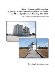
- Page 359 and 360: NAME(S): Hypergolic Maintenance and
- Page 361 and 362: PHOTOGRAPHS: Photo 1. View showing
- Page 363 and 364: Location Map: Hypergolic Maintenanc
- Page 365 and 366: opens onto the roof of the annex. F
- Page 367 and 368: Photo 3. Platform Level 1, HMP (Nor
- Page 369 and 370: Location Map: Hypergol Module Proce
- Page 371 and 372: position aft of the ship to the hip
- Page 373 and 374: PHOTOGRAPHS: Photo 1. Retrieval Shi
- Page 375 and 376: Photo 5. Mission Specialist Stephen
- Page 377 and 378: NAME(S): Retrieval Ship Freedom Sta
- Page 379 and 380: The forecastle deck, or Deck 01, si
- Page 381 and 382: Photo 3. Retrieval Vessel, Freedom
- Page 383 and 384: Photo 7. Mission Specialist Stephen
- Page 385: NAME(S): Mobile Launcher Platform (
- Page 389 and 390: Photo 3. MLP during renovations for
- Page 391 and 392: Photo 7. MLP at Launch Pad 39A, dur
- Page 393 and 394: Space Shuttle Program Historic Prop
- Page 395 and 396: Page 1 Ent D (FMSF only)___/___/___
- Page 397 and 398: SURVEY LOG SHEET ATTACHMENT Previou
- Page 399 and 400: Space Shuttle Program Historic Prop
- Page 401: Space Shuttle Program Historic Prop