Evaluation and Repair of Wrought Iron and - Purdue e-Pubs ...
Evaluation and Repair of Wrought Iron and - Purdue e-Pubs ...
Evaluation and Repair of Wrought Iron and - Purdue e-Pubs ...
You also want an ePaper? Increase the reach of your titles
YUMPU automatically turns print PDFs into web optimized ePapers that Google loves.
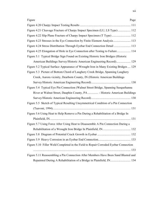
xiiFigurePageFigure 4.20 Charpy Impact Testing Results ................................................................... 111Figure 4.21 Cleavage Fracture <strong>of</strong> Charpy Impact Specimen (LU, LS Type)................. 112Figure 4.22 Slip Plane Fracture <strong>of</strong> Charpy Impact Specimen (T Type) ......................... 112Figure 4.23 Stresses in the Eye Connection by Finite Element Analysis....................... 113Figure 4.24 Stress Distribution Through Eyebar End Connection Detail ...................... 113Figure 4.25 Elongation <strong>of</strong> Hole in Eye Connection after Testing to Failure.................. 114Figure 5.1 Typical Bridge Sign Found on Existing Historic <strong>Iron</strong> Bridges (HistoricAmerican Buildings Survey/Historic American Engineering Record)................... 129Figure 5.2 Typical Surface Appearance <strong>of</strong> <strong>Wrought</strong> <strong>Iron</strong> in Many Existing Bridges .... 129Figure 5.3 Picture <strong>of</strong> Bottom Chord <strong>of</strong> Laughery Creek Bridge, Spanning LaugheryCreek, Aurora vicinity, Dearborn County, IN (Historic American BuildingsSurvey/Historic American Engineering Record).................................................... 130Figure 5.4 Typical Eye Pin Connection (Walnut Street Bridge, Spanning SusquehannaRiver at Walnut Street, Dauphin County, PA.............. - Historic American BuildingsSurvey/Historic American Engineering Record).................................................... 130Figure 5.5 Sketch <strong>of</strong> Typical Resulting Unsymmetrical Condition <strong>of</strong> a Pin Connection(Taavoni, 1994)....................................................................................................... 131Figure 5.6 Using Heat to Help Remove a Pin During a Rehabilitation <strong>of</strong> a Bridge InPlainfield, IN........................................................................................................... 131Figure 5.7 Using Force After Using Heat to Disassemble A Pin Connection During aRehabilitation <strong>of</strong> a <strong>Wrought</strong> <strong>Iron</strong> Bridge In Plainfield, IN..................................... 132Figure 5.8 Diagram <strong>of</strong> Potential Crack Growth in Eyebar ............................................ 132Figure 5.9 Heavy Corrosion in an Eyebar End Connection........................................... 133Figure 5.10 Filler Weld Completed in the Field to <strong>Repair</strong> Corroded Eyebar Connection................................................................................................................................. 133Figure 5.11 Reassembling a Pin Connection After Members Have Been S<strong>and</strong> Blasted <strong>and</strong>Repainted During A Rehabilitation <strong>of</strong> a Bridge in Plainfield, IN........................... 134


