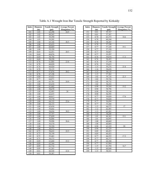
152Table A.1 <strong>Wrought</strong> <strong>Iron</strong> Bar Tensile Strength Reported by KirkaldyIndex Diameter Tensile Strength Average Percent Index Diameter Tensile Strength Average Percent(in) (psi) Elongation (%) (in) (psi) Elongation (%)101 1.03 62,298 24.9 151 0.81 59,767102 1.02 60,565 152 0.81 57,387103 1.03 59,390 153 0.70 63,373 18.6104 1.03 59,202 154 0.70 60,244105 1.00 65,166 26.5 155 0.70 58,207106 1.00 62,635 156 0.70 57,188107 1.00 60,069 157 0.77 57,328 19.1108 1.00 59,320 158 0.77 57,328109 0.69 62,451 20.5 159 0.77 56,667110 0.69 60,876 160 0.77 55,297111 0.69 58,756 161 0.76 59,070 17.3112 0.69 58,228 162 0.76 58,452113 0.78 61,805 23.8 163 0.76 57,190114 0.78 60,020 164 0.76 55,653115 0.78 60,020 165 1.15 59,276 23.8116 0.78 59,135 166 1.16 58,658117 0.77 67,876 20.2 167 1.15 58,135118 0.78 67,198 168 1.15 57,362119 0.80 65,622 169 1.02 59,726 22.3120 0.77 64,871 170 1.02 59,726121 1.00 65,701 24.4 171 1.02 58,732122 1.00 63,634 172 1.02 58,252123 1.00 61,602 173 0.90 59,104 19.2124 1.00 58,678 174 0.90 58,796125 1.00 62,885 26 175 0.90 58,180126 1.00 62,635 176 0.90 56,595127 1.00 60,817 177 0.77 59,820 17.6128 1.00 59,570 178 0.77 59,820129 1.00 64,133 25.6 179 0.77 56,694130 1.00 64,133 180 0.77 53,266131 1.00 63,634 181 1.13 64,575 17132 1.00 59,642 182 1.12 62,495133 1.00 58,036 30.2 183 1.13 62,201134 1.00 57,757 184 1.13 54,245135 1.00 57,039 185 1.01 66,363 19.1136 1.00 56,004 186 1.01 64,895137 1.00 59,998 26.6 187 1.00 60,069138 1.00 59,570 188 1.00 60,069139 1.00 59,320 189 0.90 62,229 20140 1.00 58,571 190 0.90 62,229141 0.75 58,632 22.5 191 0.89 60,453142 0.75 58,190 192 0.89 60,453143 0.75 55,463 193 0.77 66,553 17.3144 0.75 54,575 194 0.77 66,373145 0.89 63,604 22.2 195 0.77 64,390146 0.89 62,344 196 0.77 61,864147 0.89 61,714 197 1.15 61,594 16.7148 0.89 61,263 198 1.15 60,840149 0.81 60,528 22.4 199 1.15 58,521150 0.81 59,387
153Table A.1 (continued) <strong>Wrought</strong> <strong>Iron</strong> Bar Tensile Strength Reported by KirkaldyIndex Diameter Tensile Strength Average Percent Index Diameter Tensile Strength Average Percent(in) (psi) Elongation (%) (in) (psi) Elongation (%)200 1.15 52,348 250 0.70 55,078201 1.04 60,722 16.4 251 0.75 59,330202 1.02 59,965 252 0.75 58,000203 1.04 59,272 253 0.75 58,000 19.4204 1.02 57,738 254 0.75 54,766205 0.90 66,683 15.8 255 0.75 52,547206 0.90 63,505 256 0.75 51,596207 0.90 62,845 257 0.75 48,870 16.6208 0.90 62,845 258 0.75 47,095209 0.77 63,547 18.8 259 0.67 62,411210 0.77 62,705 260 0.71 60,621211 0.77 61,804 261 0.70 60,317 17.7212 0.77 59,493 262 0.74 59,512213 1.00 60,817 23.2 263 0.74 57,690214 1.00 59,569 264 0.90 48,987215 1.00 59,569 265 0.90 47,664 21.6216 0.98 58,351 266 0.90 47,384217 0.99 56,121 21.3 267 0.90 47,384218 0.92 61,296 268 0.91 49,505219 0.92 61,296 269 0.93 49,022 16.9220 0.92 57,134 270 0.92 47,534221 0.92 55,913 23.7 271 0.90 46,869222 0.87 58,823 272 0.89 55,190223 0.87 56,515 273 0.91 49,049 27.8224 0.87 56,515 274 0.89 49,418225 0.87 56,515 21.3 275 0.88 44,600226 0.78 60,695 276 0.91 65,516227 0.77 60,541 277 0.95 56,447 26.4228 0.77 59,700 278 0.92 52,923229 0.72 57,976 23.7 279 0.92 52,334230 0.79 56,316 280 0.76 54,070231 0.76 61,106 281 0.75 53,739 13.3232 0.76 59,316 282 0.76 53,205233 0.76 58,884 20.9 283 0.77 52,665234 0.75 58,886 284 0.76 57,526235 0.75 63,577 285 0.75 57,290 15.3236 0.75 62,626 286 0.75 54,626237 0.75 61,678 16.9 287 0.76 54,070238 0.75 59,013 288 0.88 49,671239 0.75 59,900 289 0.87 47,519 24.8240 0.75 59,457 290 0.87 49,167241 0.75 59,013 21.6 291 0.86 45,234242 0.75 58,506 292 1.00 47,459243 0.81 68,848 293 1.00 46,450 16.6244 0.81 56,104 294 1.00 44,703245 0.81 55,726 19.4 295 1.00 44,453246 0.81 47,248 296 .75*1 58,661247 0.70 59,226 297 .75*1 57,520 19.2248 0.70 58,789 298 .75*1 55,960249 0.70 56,606 21.6 299 .75*1 55,437
- Page 1 and 2:
Purdue UniversityPurdue e-PubsJTRP
- Page 3:
1. Report No. 2. Government Accessi
- Page 6 and 7:
epairing a bent wrought iron tensio
- Page 8 and 9:
vPageCHAPTER 3TEST PROCEDURES FOR M
- Page 10 and 11:
ixLIST OF FIGURESFigurePageFigure 1
- Page 12 and 13:
xiFigurePageFigure 3.30 Top View of
- Page 14 and 15:
xiiiFigurePageFigure 5.12 Typical T
- Page 16 and 17:
xvAppendix FigurePageFigure D.7 Ini
- Page 18 and 19:
viiiAppendix TablePageTable A.5 Det
- Page 20 and 21:
iiiThe authors would also like to t
- Page 22 and 23:
2but also what material properties
- Page 24 and 25:
4microstructure of the metal. The c
- Page 26 and 27:
62. LITERATURE SEARCHBefore experim
- Page 28 and 29:
8imperfections, the performance of
- Page 30 and 31:
10wrought iron. Adding the slag aft
- Page 32 and 33:
12method for manufacturing wrought
- Page 34 and 35:
14patents for their process and tra
- Page 36 and 37:
16This method of testing of structu
- Page 38 and 39:
18plot of this percent elongation d
- Page 40 and 41:
20significant variation in the perc
- Page 42 and 43:
22The practice of restoring histori
- Page 44 and 45:
24Elleby, Wallace W. Sanders, F. Wa
- Page 46 and 47:
26From all the surveys that were di
- Page 48 and 49:
28Table 2.1 Average Ultimate Streng
- Page 50 and 51:
30Figure 2.3 Wrought Iron “Sponge
- Page 52 and 53:
32Histogram of Kirkaldy Wrought Iro
- Page 54 and 55:
34Percent Occurance in Range - %45.
- Page 56 and 57:
3660Combined Wrought Iron BarsTensi
- Page 58 and 59:
38The Bell Ford Bridge consisted of
- Page 60 and 61:
40Two. These samples were taken fro
- Page 62 and 63:
42specimens were of constant cross
- Page 64 and 65:
44Along with rectangular tensile co
- Page 66 and 67:
46After the initial test loading wa
- Page 68 and 69:
483.6 Fatigue TestingTo develop a b
- Page 70 and 71:
50The final specimen category consi
- Page 72 and 73:
52This analysis was completed using
- Page 74 and 75:
54After the initial test was comple
- Page 76 and 77:
56completed, but before the surface
- Page 78 and 79:
58readings, load cell readings and
- Page 80 and 81:
60Figure 3.3 Donated Eyebars 4 and
- Page 82 and 83:
62Figure 3.7 Heated Areas in Blue o
- Page 84 and 85:
64Figure 3.11 Detail Used in Groove
- Page 86 and 87:
66900080007000y = 27.153xR 2 = 0.99
- Page 88 and 89:
68Figure 3.19 Charpy Impact Testing
- Page 90 and 91:
70Figure 3.23 Eyebar Connection in
- Page 92 and 93:
72Figure 3.27 Eyebar A After Filler
- Page 94 and 95:
74Figure 3.31 Side View of Finished
- Page 96 and 97:
76Figure 3.35 Front View of Eyebar
- Page 98 and 99:
78strength from the existence of pe
- Page 100 and 101:
80The carbon content present in the
- Page 102 and 103:
82value may not be very accurate bu
- Page 104 and 105:
84strengths was found to be 29,940
- Page 106 and 107:
86wrought iron bars were investigat
- Page 108 and 109:
88stresses are induced. These perma
- Page 110 and 111:
90toughness the material. The test
- Page 112 and 113:
92From the finite element analysis,
- Page 114 and 115:
94Table 4.1 Chemical Analysis of Ey
- Page 116 and 117:
96Table 4.3 Tensile Coupon Test Res
- Page 118 and 119:
98Table 4.5 Charpy Impact Test Resu
- Page 120 and 121:
100Table 4.7 Comparison of Strain G
- Page 122 and 123: 102Figure 4.1 Typical Micrograph of
- Page 124 and 125: 104Figure 4.5 Fracture Surface of D
- Page 126 and 127: 106Comparison of Tensile Strengthfo
- Page 128 and 129: 108Combined Wrought Iron Bar Histor
- Page 130 and 131: 110Figure 4.17 Macrograph of Weld u
- Page 132 and 133: 112Figure 4.21 Cleavage Fracture of
- Page 134 and 135: Figure 4.25 Elongation of Hole in E
- Page 136 and 137: 116signs on or near the bridge that
- Page 138 and 139: 118testing of historic wrought iron
- Page 140 and 141: 120so that they would act in symmet
- Page 142 and 143: 122The reasons for the differences
- Page 144 and 145: 124The second corrosion pattern mod
- Page 146 and 147: 126Keating (1984) stated that the s
- Page 148 and 149: 128charcoal fire until it is red ho
- Page 150 and 151: 130Figure 5.3 Picture of Bottom Cho
- Page 152 and 153: 132Figure 5.7 Using Force After Usi
- Page 154 and 155: 134Figure 5.11 Reassembling a Pin C
- Page 156 and 157: 1366. SUMMARY, CONCLUSIONS AND IMPL
- Page 158 and 159: 138rectangular in shape. These eyeb
- Page 160 and 161: 140were joined together with a full
- Page 162 and 163: 1424. The Charpy impact energy of t
- Page 164 and 165: 144connections are unsymmetrical, i
- Page 166 and 167: 146LIST OF REFERENCESAASHTO (1998).
- Page 168 and 169: 148Hodgkinson, Eaton (1840). Experi
- Page 170 and 171: 150Appendix A. Data Collected From
- Page 174 and 175: 154Table A.1 (continued) Wrought Ir
- Page 176 and 177: 156Table A.2 (continued) Wrought Ir
- Page 178 and 179: 158Table A.3 Wrought Iron Angle Ten
- Page 180 and 181: 160Table A.4 (continued) Summary of
- Page 182 and 183: 162Table A.4 (continued) Summary of
- Page 184 and 185: 164Table A.5 (continued) Detailed I
- Page 186 and 187: 166Table A.5 (continued) Detailed I
- Page 188 and 189: 168Table A.5 (continued) Detailed I
- Page 190 and 191: 170Table A.5 (continued) Detailed I
- Page 192 and 193: 172Table A.5 (continued) Detailed I
- Page 194 and 195: 174Table A.5 (continued) Detailed I
- Page 196 and 197: 176Table A.5 (continued) Detailed I
- Page 198 and 199: 178Table A.5 (continued) Detailed I
- Page 200 and 201: 180Table A.5 (continued) Detailed I
- Page 202 and 203: 182Table A.5 (continued) Detailed I
- Page 204 and 205: 184Table A.7 Tensile Strength Data
- Page 206 and 207: 186Table B.1 Example Historic Wroug
- Page 208 and 209: 188DepartmentofTransportationIf you
- Page 210 and 211: 190CountyIf your organizationdoes m
- Page 212 and 213: 192County 16: County bridge inspect
- Page 214 and 215: 194State 13: Included in original d
- Page 216 and 217: 196Figure C.1 Diagrams Showing Loca
- Page 218 and 219: 198Figure C.3 Heating of Eyebar fro
- Page 220 and 221: 200Figure C.7 Double V Butt Joint u
- Page 222 and 223:
202Figure C. 11 Welded Tensile Coup
- Page 224 and 225:
204Figure C.15 Tensile Coupon from
- Page 226 and 227:
206Figure C.19 Cooling Bath with Su
- Page 228 and 229:
208Figure C.23 Side View of Eyebar
- Page 230 and 231:
210Figure C.27 Eyebar End Connectio
- Page 232 and 233:
212Appendix D. Welding Procedure fo
- Page 234 and 235:
214D.2 Filler Weld for Eyebar Conne
- Page 236 and 237:
216Figure D.1 Weld Joint Detail Use
- Page 238 and 239:
Figure D.5 Completed Weld Before Su
- Page 240 and 241:
220Figure D.7 Initial Pass Pattern