- Page 1 and 2:
Purdue UniversityPurdue e-PubsJTRP
- Page 3:
1. Report No. 2. Government Accessi
- Page 6 and 7:
epairing a bent wrought iron tensio
- Page 8 and 9:
vPageCHAPTER 3TEST PROCEDURES FOR M
- Page 10 and 11:
ixLIST OF FIGURESFigurePageFigure 1
- Page 12 and 13:
xiFigurePageFigure 3.30 Top View of
- Page 14 and 15:
xiiiFigurePageFigure 5.12 Typical T
- Page 16 and 17:
xvAppendix FigurePageFigure D.7 Ini
- Page 18 and 19:
viiiAppendix TablePageTable A.5 Det
- Page 20 and 21:
iiiThe authors would also like to t
- Page 22 and 23:
2but also what material properties
- Page 24 and 25:
4microstructure of the metal. The c
- Page 26 and 27:
62. LITERATURE SEARCHBefore experim
- Page 28 and 29:
8imperfections, the performance of
- Page 30 and 31:
10wrought iron. Adding the slag aft
- Page 32 and 33:
12method for manufacturing wrought
- Page 34 and 35:
14patents for their process and tra
- Page 36 and 37:
16This method of testing of structu
- Page 38 and 39:
18plot of this percent elongation d
- Page 40 and 41:
20significant variation in the perc
- Page 42 and 43:
22The practice of restoring histori
- Page 44 and 45:
24Elleby, Wallace W. Sanders, F. Wa
- Page 46 and 47:
26From all the surveys that were di
- Page 48 and 49:
28Table 2.1 Average Ultimate Streng
- Page 50 and 51:
30Figure 2.3 Wrought Iron “Sponge
- Page 52 and 53:
32Histogram of Kirkaldy Wrought Iro
- Page 54 and 55:
34Percent Occurance in Range - %45.
- Page 56 and 57:
3660Combined Wrought Iron BarsTensi
- Page 58 and 59:
38The Bell Ford Bridge consisted of
- Page 60 and 61:
40Two. These samples were taken fro
- Page 62 and 63:
42specimens were of constant cross
- Page 64 and 65:
44Along with rectangular tensile co
- Page 66 and 67:
46After the initial test loading wa
- Page 68 and 69:
483.6 Fatigue TestingTo develop a b
- Page 70 and 71:
50The final specimen category consi
- Page 72 and 73:
52This analysis was completed using
- Page 74 and 75:
54After the initial test was comple
- Page 76 and 77:
56completed, but before the surface
- Page 78 and 79:
58readings, load cell readings and
- Page 80 and 81:
60Figure 3.3 Donated Eyebars 4 and
- Page 82 and 83:
62Figure 3.7 Heated Areas in Blue o
- Page 84 and 85:
64Figure 3.11 Detail Used in Groove
- Page 86 and 87:
66900080007000y = 27.153xR 2 = 0.99
- Page 88 and 89:
68Figure 3.19 Charpy Impact Testing
- Page 90 and 91:
70Figure 3.23 Eyebar Connection in
- Page 92 and 93:
72Figure 3.27 Eyebar A After Filler
- Page 94 and 95:
74Figure 3.31 Side View of Finished
- Page 96 and 97:
76Figure 3.35 Front View of Eyebar
- Page 98 and 99:
78strength from the existence of pe
- Page 100 and 101:
80The carbon content present in the
- Page 102 and 103:
82value may not be very accurate bu
- Page 104 and 105:
84strengths was found to be 29,940
- Page 106 and 107:
86wrought iron bars were investigat
- Page 108 and 109:
88stresses are induced. These perma
- Page 110 and 111:
90toughness the material. The test
- Page 112 and 113:
92From the finite element analysis,
- Page 114 and 115:
94Table 4.1 Chemical Analysis of Ey
- Page 116 and 117:
96Table 4.3 Tensile Coupon Test Res
- Page 118 and 119:
98Table 4.5 Charpy Impact Test Resu
- Page 120 and 121:
100Table 4.7 Comparison of Strain G
- Page 122 and 123:
102Figure 4.1 Typical Micrograph of
- Page 124 and 125:
104Figure 4.5 Fracture Surface of D
- Page 126 and 127:
106Comparison of Tensile Strengthfo
- Page 128 and 129:
108Combined Wrought Iron Bar Histor
- Page 130 and 131:
110Figure 4.17 Macrograph of Weld u
- Page 132 and 133:
112Figure 4.21 Cleavage Fracture of
- Page 134 and 135:
Figure 4.25 Elongation of Hole in E
- Page 136 and 137:
116signs on or near the bridge that
- Page 138 and 139:
118testing of historic wrought iron
- Page 140 and 141:
120so that they would act in symmet
- Page 142 and 143:
122The reasons for the differences
- Page 144 and 145:
124The second corrosion pattern mod
- Page 146 and 147:
126Keating (1984) stated that the s
- Page 148 and 149:
128charcoal fire until it is red ho
- Page 150 and 151:
130Figure 5.3 Picture of Bottom Cho
- Page 152 and 153:
132Figure 5.7 Using Force After Usi
- Page 154 and 155:
134Figure 5.11 Reassembling a Pin C
- Page 156 and 157:
1366. SUMMARY, CONCLUSIONS AND IMPL
- Page 158 and 159:
138rectangular in shape. These eyeb
- Page 160 and 161:
140were joined together with a full
- Page 162 and 163:
1424. The Charpy impact energy of t
- Page 164 and 165:
144connections are unsymmetrical, i
- Page 166 and 167:
146LIST OF REFERENCESAASHTO (1998).
- Page 168 and 169:
148Hodgkinson, Eaton (1840). Experi
- Page 170 and 171:
150Appendix A. Data Collected From
- Page 172 and 173:
152Table A.1 Wrought Iron Bar Tensi
- Page 174 and 175:
154Table A.1 (continued) Wrought Ir
- Page 176 and 177:
156Table A.2 (continued) Wrought Ir
- Page 178 and 179:
158Table A.3 Wrought Iron Angle Ten
- Page 180 and 181:
160Table A.4 (continued) Summary of
- Page 182 and 183: 162Table A.4 (continued) Summary of
- Page 184 and 185: 164Table A.5 (continued) Detailed I
- Page 186 and 187: 166Table A.5 (continued) Detailed I
- Page 188 and 189: 168Table A.5 (continued) Detailed I
- Page 190 and 191: 170Table A.5 (continued) Detailed I
- Page 192 and 193: 172Table A.5 (continued) Detailed I
- Page 194 and 195: 174Table A.5 (continued) Detailed I
- Page 196 and 197: 176Table A.5 (continued) Detailed I
- Page 198 and 199: 178Table A.5 (continued) Detailed I
- Page 200 and 201: 180Table A.5 (continued) Detailed I
- Page 202 and 203: 182Table A.5 (continued) Detailed I
- Page 204 and 205: 184Table A.7 Tensile Strength Data
- Page 206 and 207: 186Table B.1 Example Historic Wroug
- Page 208 and 209: 188DepartmentofTransportationIf you
- Page 210 and 211: 190CountyIf your organizationdoes m
- Page 212 and 213: 192County 16: County bridge inspect
- Page 214 and 215: 194State 13: Included in original d
- Page 216 and 217: 196Figure C.1 Diagrams Showing Loca
- Page 218 and 219: 198Figure C.3 Heating of Eyebar fro
- Page 220 and 221: 200Figure C.7 Double V Butt Joint u
- Page 222 and 223: 202Figure C. 11 Welded Tensile Coup
- Page 224 and 225: 204Figure C.15 Tensile Coupon from
- Page 226 and 227: 206Figure C.19 Cooling Bath with Su
- Page 228 and 229: 208Figure C.23 Side View of Eyebar
- Page 230 and 231: 210Figure C.27 Eyebar End Connectio
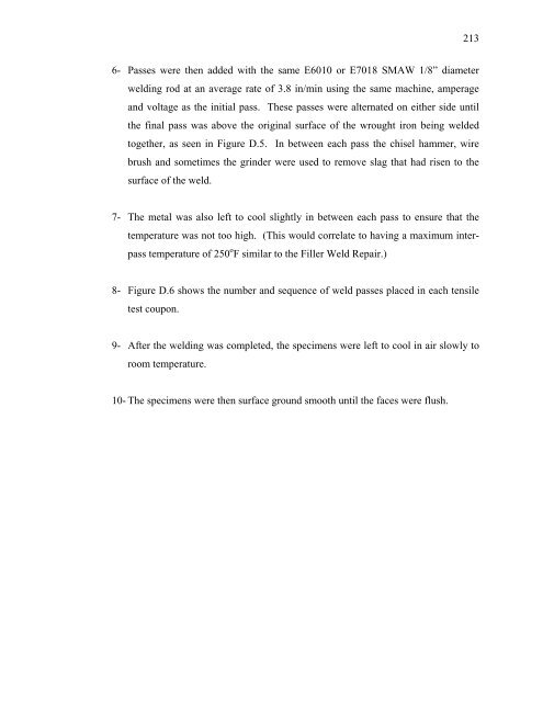
- Page 234 and 235: 214D.2 Filler Weld for Eyebar Conne
- Page 236 and 237: 216Figure D.1 Weld Joint Detail Use
- Page 238 and 239: Figure D.5 Completed Weld Before Su
- Page 240 and 241: 220Figure D.7 Initial Pass Pattern


