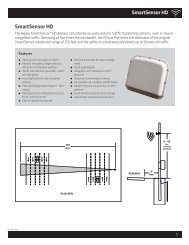
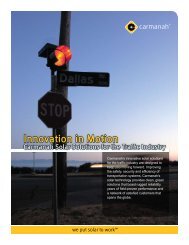
SmartSensor HD - Interprovincial Traffic Services
SmartSensor HD - Interprovincial Traffic Services
SmartSensor HD - Interprovincial Traffic Services

You also want an ePaper? Increase the reach of your titles
YUMPU automatically turns print PDFs into web optimized ePapers that Google loves.
CHAPTER 2 • CONNECTING POWER AND SURGE 23GND/-DC (Black)+DC (Red)+485 (White)-485 (Blue)Power DrainRS-485 DrainGround (Gray)RTS (Orange)CTS (Brown)RD (Purple)TD (Yellow)CTS (Brown)RTS (Orange)TD (Yellow)RD (Purple)-485 (Blue)+485 (White)Ground (Gray)RS-485 Drain+DC (Red)-DC (Black)RS-232 DrainPower DrainFigure 2.3 – Click 200 Terminal Connections (protected and unprotected sides)If you have an 8-conductor cable, it will have the following wiring differences:˽˽˽˽˽˽There is no gray ground wire.Instead of three drains, there is only one. This drain can be connected into any of thescrew terminals marked GND.The white +485 wire will have a blue stripe.NoteSee Appendices A and B for cable pinout diagrams for the 8-conductor cable and the9-conductor cable.Wiring to Earth GroundAll Click 200 devices should be mounted on a DIN rail that is connected to earth groundeither through an earth-grounded chassis or a 16 AWG or larger grounding wire attachedto a 7-ft. (2.1-m) grounding rod. Follow the steps below to correctly wire to earth ground:1 Connect the grounding wire from either the DIN rail or a GND screw terminal onthe UNPROTECTED side of the Click 200 to the lug bolt on the inside of the polemountcabinet.2 Connect another grounding wire from the exterior lug bolt to earth ground (see Figure2.4).