

Boiler Manual - Weil-McLain
Boiler Manual - Weil-McLain
Boiler Manual - Weil-McLain

You also want an ePaper? Increase the reach of your titles
YUMPU automatically turns print PDFs into web optimized ePapers that Google loves.
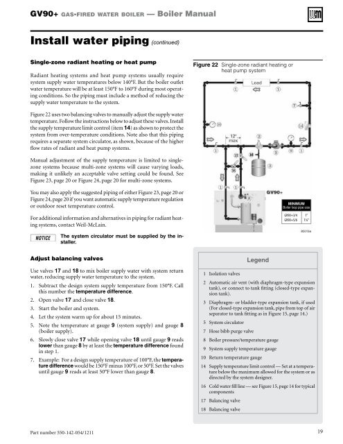
GV90+ gas-fired water boiler — <strong>Boiler</strong> <strong>Manual</strong>Install water piping (continued)Single-zone radiant heating or heat pumpRadiant heating systems and heat pump systems usually requiresystem supply water temperatures below 140°F. But the boiler outletwater temperature will be at least 150°F to 160°F during most operatingconditions. So the piping must include a method of reducing thesupply water temperature to the system.Figure 22 Single-zone radiant heating orheat pump systemFigure 22 uses two balancing valves to manually adjust the supply watertemperature. Follow the instructions below to adjust these valves. Installthe supply temperature limit control (item 14) as shown to protect thesystem from over-temperature conditions. Note also that this pipingrequires a separate system circulator, as shown, because of the higherflow rates of radiant and heat pump systems.<strong>Manual</strong> adjustment of the supply temperature is limited to singlezonesystems because multi-zone systems will cause varying loads,making it unlikely an acceptable valve setting could be found. SeeFigure 23, page 20 or Figure 24, page 20 for multi-zone systems.You may also apply the suggested piping of either Figure 23, page 20 orFigure 24, page 20 if you want automatic supply temperature regulationor outdoor reset temperature control.MINIMUM<strong>Boiler</strong> loop pipe sizeFor additional information and alternatives in piping for radiant heatingsystems, contact <strong>Weil</strong>-<strong>McLain</strong>.The system circulator must be supplied by the installer.GV90+3/4GV90+5/61”1¼”Adjust balancing valvesUse valves 17 and 18 to mix boiler supply water with system returnwater, reducing supply water temperature to the system.1. Subtract the design system supply temperature from 150°F. Callthis number the temperature difference.2. Open valve 17 and close valve 18.3. Start the boiler and system.4. Let the system warm up for about 15 minutes.5. Note the temperature at gauge 9 (system supply) and gauge 8(boiler supply).6. Slowly close valve 17 while opening valve 18 until gauge 9 readslower than gauge 8 by at least the temperature difference foundin step 1.7. Example: For a design supply temperature of 100°F, the temperaturedifference would be 150°F minus 100°F, or 50°F. Set the valvesuntil gauge 9 reads at least 50°F lower than gauge 8.1 Isolation valvesLegend2 Automatic air vent (with diaphragm-type expansiontank), or connect to tank fitting (closed-type expansiontank).3 Diaphragm- or bladder-type expansion tank, if used(For closed-type expansion tank, pipe from top of airseparator to tank fitting as in Figure 15, page 14.)5 System circulator7 Hose bibb purge valve8 <strong>Boiler</strong> pressure/temperature gauge9 System supply temperature gauge10 Return temperature gauge14 Supply temperature limit control — Set at a temperaturebelow the maximum allowed for the system or asdirected by the system designer.16 Cold water fill line — see Figure 15, page 14 for typicalcomponents17 Balancing valve18 Balancing valvePart number 550-142-054/1211 19


