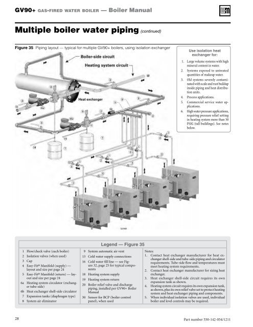
GV90+ gas-fired water boiler — <strong>Boiler</strong> <strong>Manual</strong>Multiple boiler water piping (continued)Figure 35 Piping layout — typical for multiple GV90+ boilers, using isolation exchangerUse isolation heatexchanger for:1. Large volume systems with highmineral content in water.2. Systems exposed to untreatedquantities of makeup water.3. Old systems severely contaminatedwith scale and rust buildupinside piping and heat distributionunits.4. Process applications.5. Commercial service water applications.6. High water pressure applications,requiring pressure relief settingin heating system more than 50PSIG (tall buildings). See notesbelow.Legend — Figure 351 Flow/check valve (each boiler)2 Isolation valves (when used)3 Cap4 Easy-Fit® Manifold (supply) —layout and size per page 245 Easy-Fit® Manifold (return) — layoutand size per page 246a Heating system circulator (exchangertube-side)6b Heat exchanger shell-side circulator7 Expansion tanks (diaphragm type)8 System air eliminator9 System automatic air vent13 Cold water supply connections16 Cold water fill line — see Figure32, page 25 for typical components18 Heating system supply19 Heating system return20 <strong>Boiler</strong> relief valve and dischargepiping, installed per GV90+ <strong>Boiler</strong><strong>Manual</strong>30 Sensor for BCP (boiler controlpanel), when usedNotes:1. Contact heat exchanger manufacturer for heat exchangershell-side and tube-side piping and circulatorrequirements. Tube-side flow and temperatures mustmeet heating system requirements.2. Contact heat exchanger manufacturer for sizing heatexchanger.3. Heat exchanger shell-side circuit requires its ownexpansion tank as shown.4. Heating system circuit requires its own expansion tank,as shown, plus its own relief valve set to protect heatingsystem and heat exchanger piping and components.5. When individual isolation valves are used, individualboiler and level controls may be required.28Part number 550-142-054/1211
GV90+ gas-fired water boiler — <strong>Boiler</strong> <strong>Manual</strong>Venting & air — generalGV90+ boilers must be vented andsupplied with combustion and ventilationair using piping and methodsdescribed in this manual.Every boiler must have its own vent.DO NOT common vent with any otherappliance.Inspect finished vent and air pipingthoroughly to ensure all are airtightand comply with the instructionsprovided and with all requirements ofapplicable codes.Failure to provide a properly-installedvent and air system will cause severepersonal injury or death.If the vent/air piping configurationscovered in the GV90+ boiler manualcannot be applied for a particularinstallation, contact <strong>Weil</strong>-<strong>McLain</strong> forassistance. Other configurations maybe available.Where vent piping is routed throughan unheated space, apply minimum1 inch of foil-faced fiberglass insulationon the length of the vent pipe in theunheated space.Installations must comply with localrequirements and with the NationalFuel Gas Code, ANSI Z223.1 for U.S.installations or CSA B149.1 or B149.2for Canadian installations.Use only the materials listed in thismanual for vent and air pipe and fittings.See Figure 40, page 33.If used, a masonry chimney canONLY be used as a PIPE CHASE forvent and air pipes — The vent and airpiping must be installed as instructedin this manual and all joints must besealed. The chimney must be usedonly for GV90+ boilers. NO OTHERappliance or fireplace can be connectedto the chimney. The chimney must bestraight, with no offsets, and the ventand air piping materials must complywith this instruction manual. Thechimney must be fitted with a sealedaccess opening, through which the interiorof the chimney can be inspected.The chimney (and liner, if installed)must be inspected at least once annuallyto verify condition.Failure to comply could result in severepersonal injury, death or substantialproperty damage.When removing a boiler from an existingcommon vent systemThe GV90+ boiler cannot be common vented with any otherappliance. When an existing boiler is replaced with a GV90+ boiler,the GV90+ boiler CANNOT use the existing common vent. The GV90+boiler requires its own vent and air piping, as specified in this manual. Thismay cause a problem for the appliances that remain on the old commonvent, because the vent may be too large. The following test, required byANSI Z21.13, is intended to check for proper operation of the appliancesremaining on the old common vent system.Vent system verificationAt the time of removal of an existing boiler, the following steps shall befollowed with each appliance remaining connected to the common ventingsystem placed in operation, while the other appliances remaining connectedto the common venting system are not in operation. Seal any unused openingsin the common venting system.Existing vent test procedure(The following is intended to test whether the appliancesremaining on an existing vent system will operatesatisfactorily.)1. Visually inspect the venting system for proper size and horizontal pitchand determine there is no blockage or restriction, leakage, corrosion orother deficiencies which could cause an unsafe condition.2. Test vent system — Insofar as is practical, close all building doors andwindows and all doors between the space in which the appliancesremaining connected to the common venting system are located andother spaces of the building. Turn on clothes dryers and any appliancenot connected to the common venting system. Turn on any exhaustfans, such as range hoods and bathroom exhausts, so they will operateat maximum speed. Do not operate a summer exhaust fan. Closefireplace dampers.3. Place in operation the appliance being inspected. Follow the lighting instructions.Adjust thermostat so appliance will operate continuously.4. Test for spillage at draft hood relief opening after 5 minutes of mainburner operation. Use the flame of a match or candle, or smoke froma cigarette, cigar, or pipe.5. After it has been determined that each appliance remaining connectedto the common venting system properly vents when tested as outlinedherein, return doors, windows, exhaust fans, fireplace dampers, and anyother gas-burning appliance to their previous conditions of use.Any improper operation of common venting system should be correctedso the installation conforms with the National Fuel Gas Code, ANSI Z223.1— latest edition. Correct by re-sizing to approach the minimum size asdetermined using the appropriate tables in Part 11 of that code. Canadianinstallations must comply with B149.1 or B149.2 Installation Code.Part number 550-142-054/1211 29