

Boiler Manual - Weil-McLain
Boiler Manual - Weil-McLain
Boiler Manual - Weil-McLain

Create successful ePaper yourself
Turn your PDF publications into a flip-book with our unique Google optimized e-Paper software.
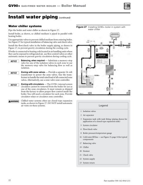
GV90+ gas-fired water boiler — <strong>Boiler</strong> <strong>Manual</strong>Install water piping (continued)Water chiller systemsPipe the boiler and water chiller as shown in Figure 27.Install boiler, as shown, so chilled medium is piped in parallel withheating boiler.Use appropriate valves to prevent chilled medium from entering boiler.See Figure 27 for typical installation of balancing valve and check valve.Install the flow/check valve in the boiler supply piping, as shown inFigure 27, to prevent gravity circulation during the cooling cycle.If boiler is connected to heating coils located in air handling units wherethey can be exposed to refrigerated air, use flow control valves or otherautomatic means to prevent gravity circulation during cooling cycle.Balancing, when required — Substitute a memory-stopvalve for one of the isolation valves in each zone to usethe memory-stop valve for balancing flow as well asisolation.Zoning with zone valves — Provide a separate 24-volttransformer to power the zone valves. Size the transformerto handle the total rated load of all connected zonevalves. Alternatively, use a zone valve zone controller.Zoning with circulators — The GV90+ internal systemcirculator cannot be removed from the boiler for use asone of the zone circulators. It must remain as shippedfrom the factory to allow proper flow control inside theboiler. You will need a circulator for each zone. Providecirculator relays or circulator zone controller.Chilled water systems often use closed-type expansiontanks, as shown in Figure 27. DO NOT install automaticair vents on these systems.Figure 27 Installing GV90+ boiler in system withwater chillerMINIMUM<strong>Boiler</strong> loop pipe sizeGV90+3/4GV90+5/61”1¼”Legend1 Isolation valves2 Air separator3 Expansion tank with tank fitting (piping shown forapplication of a closed-type expansion tank)5 System circulator6 Flow/check valve8 <strong>Boiler</strong> pressure/temperature gauge16 Cold water fill line — see Figure 15, page 14 for typicalcomponents17 Balancing valve19 Chiller20 Strainer21 Check valve22 System supply23 System return22Part number 550-142-054/1211


