

Boiler Manual - Weil-McLain
Boiler Manual - Weil-McLain
Boiler Manual - Weil-McLain

You also want an ePaper? Increase the reach of your titles
YUMPU automatically turns print PDFs into web optimized ePapers that Google loves.
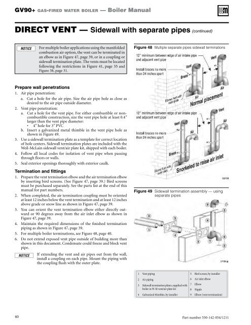
GV90+ gas-fired water boiler — <strong>Boiler</strong> <strong>Manual</strong>DIRECT VENT — Sidewall with separate pipes (continued)For multiple boiler applications using the manifoldedcombustion air option, the vent can be terminated inan elbow as in Figure 47, page 39, or in a coupling orsidewall termination plate. The vents must be locatedfollowing the restrictions in Figure 41, page 35 andFigure 38, page 31.Figure 48 Multiple separate pipes sidewall terminationsPrepare wall penetrations1. Air pipe penetration:a. Cut a hole for the air pipe. Size the air pipe hole as close asdesired to the air pipe outside diameter.2. Vent pipe penetration:a. Cut a hole for the vent pipe. For either combustible or noncombustibleconstruction, size the vent pipe hole at least 0.4”larger than the vent pipe diameter:• 4” hole for 3” PVCb. Insert a galvanized metal thimble in the vent pipe hole asshown in Figure 49.3. Use a sidewall termination plate as a template for correct locationof hole centers. Sidewall termination plates are included with the<strong>Weil</strong>-<strong>McLain</strong> sidewall vent/air plate kit, shipped with each boiler.4. Follow all local codes for isolation of vent pipe when passingthrough floors or walls.5. Seal exterior openings thoroughly with exterior caulk.Termination and fittings1. Prepare the vent termination elbow and the air termination elbowby inserting bird screens. (See Figure 47, page 39.) Bird screensmust be purchased separately. See the parts list at the end of thismanual for part numbers.2. When completed, the air termination coupling must be orientedat least 12 inches below the vent termination and at least 12 inchesabove grade or snow line as shown in Figure 47, page 39.3. You can orient the vent termination elbow either directly outwardor 90 degrees away from the air inlet elbow as shown inFigure 47, page 39.4. Maintain the required dimensions of the finished terminationpiping as shown in Figure 47, page 39.5. For multiple boiler terminations, see Figure 48, page 40.6. Do not extend exposed vent pipe outside of building more thanshown in this document. Condensate could freeze and block ventpipe.If extending the vent and air pipes out from the wall,install a coupling on each pipe. Mount the piping withthe coupling flush with the outer plate.Figure 49 Sidewall termination assembly — usingseparate pipes1 Vent piping2 Air piping3 Sidewall termination plates, supplied withboiler in W-M vent/air plate kit4 Galvanized thimbles, by installer5 Bird screen, by installer6 Air inlet elbow7 Elbow8 Nipple9 Elbow (vent termination)40Part number 550-142-054/1211


