

Boiler Manual - Weil-McLain
Boiler Manual - Weil-McLain
Boiler Manual - Weil-McLain

Create successful ePaper yourself
Turn your PDF publications into a flip-book with our unique Google optimized e-Paper software.
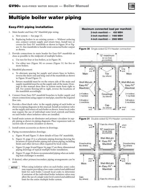
GV90+ gas-fired water boiler — <strong>Boiler</strong> <strong>Manual</strong>Multiple boiler water pipingEasy-Fit® piping installation1. Main header and Easy-Fit ® Manifold pipe sizing.a. New system — See page 15.b. Replacing boilers in an existing system — Without reducingsize, connect system supply and return lines. Install tees orcrosses for Easy-Fit ® manifolds as shown in Figure 30 or Figure31. Size manifolds to handle total connected boiler outputas shown.2. Provide connections in main header for Easy-Fit® manifolds asclose as possible to the midpoint of multiple boilers.a. Use tees for four or less boilers, as in Figure 30.b. Use either tees (Figure 30) or crosses (Figure 31) for five ormore boilers.3. Manifold placement:a. To alternate spacing for supply and return lines to boilers,reverse the short-end and long-end of the manifolds as shownin Figure 30 and Figure 31.b. Return manifold must be on the return side of the main andsupply manifold must be on the supply side of the main. Drawingsin this manual show flow in system main from right toleft. For system flowing left to right, reverse the locations ofthe manifolds accordingly.4. Connect from Easy-Fit® manifold branches to boiler supply andreturn connections using copper or steel pipe, sized for the requiredflow rate.5. Provide a flow/check valve in the supply piping of each boiler asshown in piping diagrams in this manual. Install an isolation valveon the supply and return of each boiler as shown. Some local codesmay require the use of individual water level controls and limitson each boiler when isolation valves are installed.6. Install main system air eliminator and primary circulator in supplypiping as shown in piping diagrams. Place expansion tank onsuction side of system circulator as shown.7. Install system accessories as shown in drawings.8. Piping recommendation drawings:a. Figure 30 and Figure 31 show details of Easy-Fit ® manifolds.b. Figure 32, page 25 is a schematic piping drawing showing thelocations of typical boiler piping and system piping, includinglimits and other devices often required by local codes.c. Figure 33, page 26 and Figure 34, page 27 are three-dimensionalpiping drawings of typical multiple boiler installation.d. Figure 35, page 28 shows recommended piping when an isolatingheat exchanger is needed.9. If desired, other primary/secondary piping arrangements can beused.Maximum connected load per manifold:2-inch manifold — 450 MBH3-inch manifold — 1400 MBH4-inch manifold — 2900 MBHFigure 30 Single-sided EZ-Fit Header connectionFigure 31 Double-sided EZ-Fit Header connectionWhen using isolation valves on each boiler, some codesmay require providing a low water control and additionallimit for each boiler. Consult local codes to determineif omission of the individual boiler isolation valves mayallow the use of a single water level control and additionallimit for the entire multiple boiler system.24Part number 550-142-054/1211


