Ultralow power ARM-based 32-bit MCU with 384 Kbytes Flash ... - Keil
Ultralow power ARM-based 32-bit MCU with 384 Kbytes Flash ... - Keil
Ultralow power ARM-based 32-bit MCU with 384 Kbytes Flash ... - Keil
- No tags were found...

You also want an ePaper? Increase the reach of your titles
YUMPU automatically turns print PDFs into web optimized ePapers that Google loves.
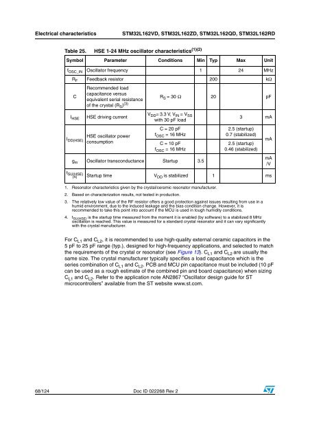
Electrical characteristicsSTM<strong>32</strong>L162VD, STM<strong>32</strong>L162ZD, STM<strong>32</strong>L162QD, STM<strong>32</strong>L162RDTable 25. HSE 1-24 MHz oscillator characteristics (1)(2)Symbol Parameter Conditions Min Typ Max Unitf OSC_IN Oscillator frequency 1 24 MHzR F Feedback resistor 200 kΩCRecommended loadcapacitance versusequivalent serial resistanceof the crystal (R S ) (3)R S = 30 Ω 20 pFI HSEI DD(HSE)HSE driving currentHSE oscillator <strong>power</strong>consumptionV DD = 3.3 V, V IN = V SS<strong>with</strong> 30 pF loadC = 20 pFf OSC = 16 MHzC = 10 pFf OSC = 16 MHzg m Oscillator transconductance Startup 3.53 mA2.5 (startup)0.7 (stabilized)2.5 (startup)0.46 (stabilized)mAmA/Vt SU(HSE)(4)Startup time V DD is stabilized 1 ms1. Resonator characteristics given by the crystal/ceramic resonator manufacturer.2. Based on characterization results, not tested in production.3. The relatively low value of the RF resistor offers a good protection against issues resulting from use in ahumid environment, due to the induced leakage and the bias condition change. However, it isrecommended to take this point into account if the <strong>MCU</strong> is used in tough humidity conditions.4. t SU(HSE) is the startup time measured from the moment it is enabled (by software) to a stabilized 8 MHzoscillation is reached. This value is measured for a standard crystal resonator and it can vary significantly<strong>with</strong> the crystal manufacturer.For C L1 and C L2 , it is recommended to use high-quality external ceramic capacitors in the5 pF to 25 pF range (typ.), designed for high-frequency applications, and selected to matchthe requirements of the crystal or resonator (see Figure 13). C L1 and C L2 are usually thesame size. The crystal manufacturer typically specifies a load capacitance which is theseries combination of C L1 and C L2 . PCB and <strong>MCU</strong> pin capacitance must be included (10 pFcan be used as a rough estimate of the combined pin and board capacitance) when sizingC L1 and C L2 . Refer to the application note AN2867 “Oscillator design guide for STmicrocontrollers” available from the ST website www.st.com.68/124 Doc ID 022268 Rev 2