Physical Principles of Electron Microscopy: An Introduction to TEM ...
Physical Principles of Electron Microscopy: An Introduction to TEM ...
Physical Principles of Electron Microscopy: An Introduction to TEM ...

Create successful ePaper yourself
Turn your PDF publications into a flip-book with our unique Google optimized e-Paper software.
118 Chapter 4<br />
High-magnification phase-contrast images are particularly valuable for<br />
examining the a<strong>to</strong>mic structure <strong>of</strong> interfaces within a solid, such as the grain<br />
boundaries within a polycrystalline material or the interface between a<br />
deposited film and its substrate; see Fig. 4-18. Sometimes the lattice fringes<br />
(which represent ordered planes <strong>of</strong> a<strong>to</strong>ms) extend right up <strong>to</strong> the boundary,<br />
indicating an abrupt interface. In other cases, they disappear a short distance<br />
from the interface, as the material becomes amorphous. Such amorphous<br />
layers can have a pr<strong>of</strong>ound effect on the mechanical or electrical properties<br />
<strong>of</strong> a material. A further type <strong>of</strong> phase-contrast image occurs in specimens<br />
that are strongly magnetic (ferromagnetic), such as iron, cobalt, and alloys<br />
containing these metals. Again, phase contrast is produced only when the<br />
specimen is defocused. The images are known as Lorentz images; they are<br />
capable <strong>of</strong> revealing the magnetic-domain structure <strong>of</strong> the specimen, which<br />
is not necessarily related <strong>to</strong> its crystallographic structure. But the objective<br />
lens <strong>of</strong> a modern <strong>TEM</strong> normally generates a high field that is likely <strong>to</strong><br />
change the domain structure, so Lorentz microscopy is usually performed<br />
with the objective turned <strong>of</strong>f or considerably weakened. With only the<br />
intermediate and projec<strong>to</strong>r lenses operating, the image magnification is<br />
relatively low.<br />
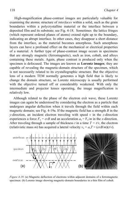
Although related <strong>to</strong> the phase <strong>of</strong> the electron exit wave, these Lorentz<br />
images can again be unders<strong>to</strong>od by considering the electron as a particle that<br />
undergoes angular deflection when it travels through the field within each<br />
magnetic domain; see Fig. 4-19a. If the magnetic field has a strength B in the<br />
y-direction, an incident electron traveling with speed v in the z-direction<br />
experiences a force Fx = evB and an acceleration ax = Fx/m in the x-direction.<br />
After traveling through a sample <strong>of</strong> thickness t in a time T = t/v, the electron<br />
(relativistic mass m) has acquired a lateral velocity vx = axT = (evB/m)(t/v).<br />
Figure 4-19. (a) Magnetic deflection <strong>of</strong> electrons within adjacent domains <strong>of</strong> a ferromagnetic<br />
specimen. (b) Lorentz image showing magnetic-domain boundaries in a thin film <strong>of</strong> cobalt.