Physical Principles of Electron Microscopy: An Introduction to TEM ...
Physical Principles of Electron Microscopy: An Introduction to TEM ...
Physical Principles of Electron Microscopy: An Introduction to TEM ...

Create successful ePaper yourself
Turn your PDF publications into a flip-book with our unique Google optimized e-Paper software.
The Transmission <strong>Electron</strong> Microscope 69<br />
To provide direct (rather than alternating) high voltage, the current from<br />
the transformer secondary is rectified by means <strong>of</strong> a series <strong>of</strong> solid-state<br />
diodes, which allow electrical current <strong>to</strong> pass only in one direction, and<br />
smoothed <strong>to</strong> remove its alternating component (ripple). Smoothing is<br />
achieved largely by the HV cable, which has enough capacitance between its<br />
inner conduc<strong>to</strong>r and the grounded outer sheath <strong>to</strong> short-circuit the ac-ripple<br />
component<br />
<strong>to</strong> ground at the operating frequency <strong>of</strong> the transformer output.<br />
Because the output <strong>of</strong> the oscilla<strong>to</strong>r circuit is linearly related <strong>to</strong> its input<br />
and rectification is also a linear process, the magnitude <strong>of</strong> the resulting<br />
accelerating voltage is given by:<br />
V0 = GVi (3.8)<br />
V+<br />
Vi +<br />
-<br />
voltagecontrolled<br />
oscilla<strong>to</strong>r<br />
I f<br />
voltagecontrolled<br />
oscilla<strong>to</strong>r<br />
I f +I e<br />
R f<br />
diodes<br />
filament<br />
R b<br />
Wehnelt<br />
-V0 HV<br />
tank<br />
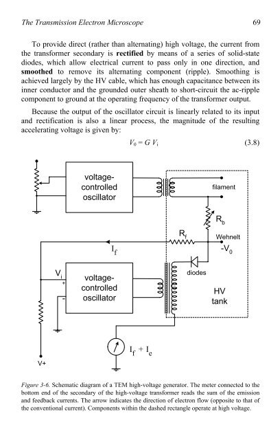
Figure 3-6. Schematic diagram <strong>of</strong> a <strong>TEM</strong> high-voltage genera<strong>to</strong>r. The meter connected <strong>to</strong> the<br />
bot<strong>to</strong>m end <strong>of</strong> the secondary <strong>of</strong> the high-voltage transformer reads the sum <strong>of</strong> the emission<br />
and feedback currents. The arrow indicates the direction <strong>of</strong> electron flow (opposite <strong>to</strong> that <strong>of</strong><br />
the conventional current). Components within the dashed rectangle operate at high voltage.