- Page 3 and 4: Ray F. Egerton Physical Principles
- Page 5 and 6: To Maia
- Page 7 and 8: viii Contents 3.3 Condenser-Lens Sy
- Page 9 and 10: PREFACE The telescope transformed o
- Page 11 and 12: Chapter 1 AN INTRODUCTION TO MICROS
- Page 13 and 14: An Introduction to Microscopy 3 In
- Page 15 and 16: An Introduction to Microscopy 5 Cha
- Page 17 and 18: An Introduction to Microscopy 7 eye
- Page 19 and 20: An Introduction to Microscopy 9 can
- Page 21 and 22: An Introduction to Microscopy 11 1.
- Page 23 and 24: An Introduction to Microscopy 13 Fi
- Page 25 and 26: An Introduction to Microscopy 15 Fi
- Page 27 and 28: An Introduction to Microscopy 17 1.
- Page 29 and 30: An Introduction to Microscopy 19 Fi
- Page 31 and 32: An Introduction to Microscopy 21 1.
- Page 33 and 34: An Introduction to Microscopy 23 A
- Page 35 and 36: An Introduction to Microscopy 25 el
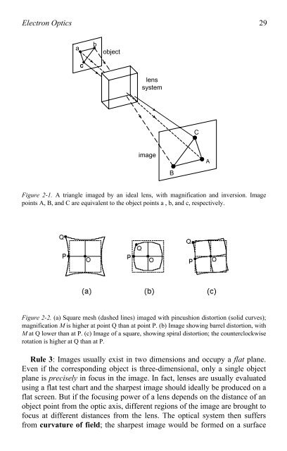
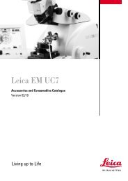
- Page 37: 28 Chapter 2 Rule 1 states that for
- Page 41 and 42: 32 Chapter 2 x 0 object principal p
- Page 43 and 44: 34 Chapter 2 2.3. Imaging with Elec
- Page 45 and 46: 36 Chapter 2 cross-product or vecto
- Page 47 and 48: 38 Chapter 2 important to remember
- Page 49 and 50: 40 Chapter 2 A cross section throug
- Page 51 and 52: 42 Chapter 2 As an example, we can
- Page 53 and 54: 44 Chapter 2 microscopes, at a time
- Page 55 and 56: 46 Chapter 2 When these non-paraxia
- Page 57 and 58: 48 Chapter 2 So far, we have said n
- Page 59 and 60: 50 Chapter 2 from the lens) for ele
- Page 61 and 62: 52 Chapter 2 P (a) P (b) y y x x +V
- Page 63 and 64: 54 Chapter 2 The stigmators found i
- Page 65 and 66: Chapter 3 THE TRANSMISSION ELECTRON
- Page 67 and 68: The Transmission Electron Microscop
- Page 69 and 70: The Transmission Electron Microscop
- Page 71 and 72: The Transmission Electron Microscop
- Page 73 and 74: The Transmission Electron Microscop
- Page 75 and 76: The Transmission Electron Microscop
- Page 77 and 78: The Transmission Electron Microscop
- Page 79 and 80: The Transmission Electron Microscop
- Page 81 and 82: The Transmission Electron Microscop
- Page 83 and 84: The Transmission Electron Microscop
- Page 85 and 86: The Transmission Electron Microscop
- Page 87 and 88: The Transmission Electron Microscop
- Page 89 and 90:
The Transmission Electron Microscop
- Page 91 and 92:
The Transmission Electron Microscop
- Page 93 and 94:
The Transmission Electron Microscop
- Page 95 and 96:
The Transmission Electron Microscop
- Page 97 and 98:
The Transmission Electron Microscop
- Page 99 and 100:
The Transmission Electron Microscop
- Page 101 and 102:
Chapter 4 TEM SPECIMENS AND IMAGES
- Page 103 and 104:
TEM Specimens and Images 95 v 0 m M
- Page 105 and 106:
TEM Specimens and Images 97 In prac
- Page 107 and 108:
TEM Specimens and Images 99 P e (>
- Page 109 and 110:
TEM Specimens and Images 101 4.4 Sc
- Page 111 and 112:
TEM Specimens and Images 103 Figure
- Page 113 and 114:
TEM Specimens and Images 105 as see
- Page 115 and 116:
TEM Specimens and Images 107 dimens
- Page 117 and 118:
TEM Specimens and Images 109 (discu
- Page 119 and 120:
TEM Specimens and Images 111 Figure
- Page 121 and 122:
TEM Specimens and Images 113 core,
- Page 123 and 124:
TEM Specimens and Images 115 unders
- Page 125 and 126:
TEM Specimens and Images 117 underf
- Page 127 and 128:
TEM Specimens and Images 119 From t
- Page 129 and 130:
TEM Specimens and Images 121 (a) (b
- Page 131 and 132:
TEM Specimens and Images 123 of a s
- Page 133 and 134:
Chapter 5 THE SCANNING ELECTRON MIC
- Page 135 and 136:
The Scanning Electron Microscope 12
- Page 137 and 138:
The Scanning Electron Microscope 12
- Page 139 and 140:
The Scanning Electron Microscope 13
- Page 141 and 142:
The Scanning Electron Microscope 13
- Page 143 and 144:
The Scanning Electron Microscope 13
- Page 145 and 146:
The Scanning Electron Microscope 13
- Page 147 and 148:
The Scanning Electron Microscope 13
- Page 149 and 150:
The Scanning Electron Microscope 14
- Page 151 and 152:
The Scanning Electron Microscope 14
- Page 153 and 154:
The Scanning Electron Microscope 14
- Page 155 and 156:
The Scanning Electron Microscope 14
- Page 157 and 158:
The Scanning Electron Microscope 14
- Page 159 and 160:
The Scanning Electron Microscope 15
- Page 161 and 162:
The Scanning Electron Microscope 15
- Page 163 and 164:
156 Chapter 6 where h = 6.63 � 10
- Page 165 and 166:
158 Chapter 6 Many-electron atoms r
- Page 167 and 168:
160 Chapter 6 Figure 6-2 also demon
- Page 169 and 170:
162 Chapter 6 x-ray computer & disp
- Page 171 and 172:
164 Chapter 6 Ideally, each peak in
- Page 173 and 174:
166 Chapter 6 to balance the units
- Page 175 and 176:
168 Chapter 6 a three-dimensional d
- Page 177 and 178:
170 Chapter 6 to be analyzed, where
- Page 179 and 180:
172 Chapter 6 different from the co
- Page 181 and 182:
174 Chapter 6 A typical energy-loss
- Page 183 and 184:
Chapter 7 RECENT DEVELOPMENTS 7.1 S
- Page 185 and 186:
Recent Developments 179 Figure 7-2.
- Page 187 and 188:
Recent Developments 181 below 0.1 n
- Page 189 and 190:
Recent Developments 183 one type of
- Page 191 and 192:
Recent Developments 185 Besides hav
- Page 193 and 194:
Recent Developments 187 Figure 7-7.
- Page 195 and 196:
Recent Developments 189 holder cont
- Page 197 and 198:
192 Appendix cathode vacuum + + + +
- Page 199 and 200:
194 Appendix The variable � repre
- Page 201 and 202:
196 References Neutze, R., Wouts, R
- Page 203 and 204:
198 Index Bright-field image, 100 B
- Page 205 and 206:
200 Index Inner-shell ionization, 1
- Page 207:
202 Index Stacking fault, 114 Stage