standards / manuals / guidelines for small hydro development - AHEC
standards / manuals / guidelines for small hydro development - AHEC
standards / manuals / guidelines for small hydro development - AHEC

You also want an ePaper? Increase the reach of your titles
YUMPU automatically turns print PDFs into web optimized ePapers that Google loves.
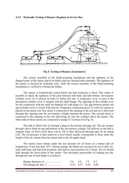
4.5.5 Hydraulic Testing of Runner (Kaplan) in Service BayFig 4: Testing of Runner [Goncharov]The correct assembly of the blade-actuating mechanism and the tightness of theflanged joints of the runner and of its blade seals are checked after assembly. The tightness ofthe runner is checked by hydraulic tests, while the correct assembly of the blade-actuatingmechanism is verified by rotating the blades.The runner is hydraulically tested be<strong>for</strong>e the hub extension is fitted. This makes itpossible to check the tightness of the joint between hub body and hub bottom. Servomotorcylinder cover (2) is placed on hub (1) be<strong>for</strong>e the test. A temporary cover is used if thepermanent cylinder cover is integral with the shaft flange. The openings in the cylinder over<strong>for</strong> the connection with the shaft are blanked off with plugs (3). The gap between piston rodand cylinder cover is closed with seal (4). Temporary connecting piece (5) with two unions isplaced on the piston rod. One union is connected to the opening in the rod and oil is deliveredthrough this opening into the servomotor cylinder beneath the piston. The second union isconnected to the opening in the rod, delivering oil into the cylinder above the piston. Theother ends of these unions are connected to pump (7) via hoses (6) (Fig. 4).The hub is filled with oil through a plug in the bottom and pipe (8). The air escapesthrough valves fitted on top and bottom of the servomotor cylinder. Oil delivery to the hub isstopped when oil flows from these valves. Oil is then delivered through pipe (9) by pump(10). The oil pressure is thus raised to a level which usually corresponds to three times theheight of the oil column from the runner hub to the oil supply head.The runner must remain under the test pressure <strong>for</strong> 24 hours at a runner and oiltemperature of not less than 10 o C. During testing, the blades are successively set to their noload,half-load, and full-load positions, and held in each position <strong>for</strong> 8 hours. No oil shouldleak through the fixed joints of the runner. The maximum permissible oil leakage per daythrough the seal of each blade is as follows:Runner diameter, m ………………. 3.0 5.0 7.2 9.3Oil leakage per day, 1…………….. 0.10 0.15 0.18 0.20<strong>AHEC</strong>/MNRE/SHP Standards/ E&M Works – Guidelines <strong>for</strong> Operation and Maintenance of Small Hydropower Station 59