standards / manuals / guidelines for small hydro development - AHEC
standards / manuals / guidelines for small hydro development - AHEC
standards / manuals / guidelines for small hydro development - AHEC

You also want an ePaper? Increase the reach of your titles
YUMPU automatically turns print PDFs into web optimized ePapers that Google loves.
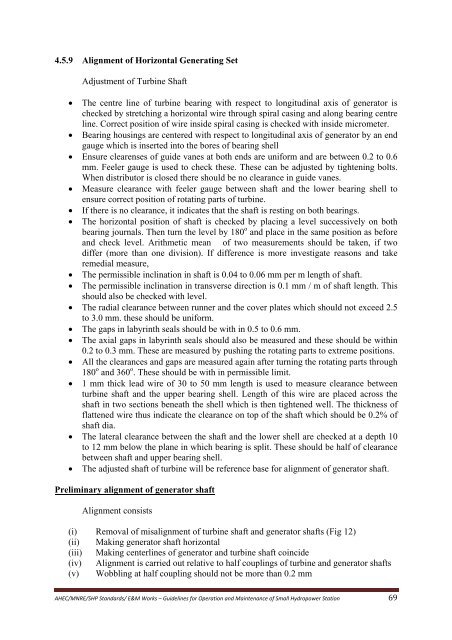
4.5.9 Alignment of Horizontal Generating SetAdjustment of Turbine Shaft• The centre line of turbine bearing with respect to longitudinal axis of generator ischecked by stretching a horizontal wire through spiral casing and along bearing centreline. Correct position of wire inside spiral casing is checked with inside micrometer.• Bearing housings are centered with respect to longitudinal axis of generator by an endgauge which is inserted into the bores of bearing shell• Ensure clearenses of guide vanes at both ends are uni<strong>for</strong>m and are between 0.2 to 0.6mm. Feeler gauge is used to check these. These can be adjusted by tightening bolts.When distributor is closed there should be no clearance in guide vanes.• Measure clearance with feeler gauge between shaft and the lower bearing shell toensure correct position of rotating parts of turbine.• If there is no clearance, it indicates that the shaft is resting on both bearings.• The horizontal position of shaft is checked by placing a level successively on bothbearing journals. Then turn the level by 180 o and place in the same position as be<strong>for</strong>eand check level. Arithmetic mean of two measurements should be taken, if twodiffer (more than one division). If difference is more investigate reasons and takeremedial measure,• The permissible inclination in shaft is 0.04 to 0.06 mm per m length of shaft.• The permissible inclination in transverse direction is 0.1 mm / m of shaft length. Thisshould also be checked with level.• The radial clearance between runner and the cover plates which should not exceed 2.5to 3.0 mm. these should be uni<strong>for</strong>m.• The gaps in labyrinth seals should be with in 0.5 to 0.6 mm.• The axial gaps in labyrinth seals should also be measured and these should be within0.2 to 0.3 mm. These are measured by pushing the rotating parts to extreme positions.• All the clearances and gaps are measured again after turning the rotating parts through180 o and 360 o . These should be with in permissible limit.• 1 mm thick lead wire of 30 to 50 mm length is used to measure clearance betweenturbine shaft and the upper bearing shell. Length of this wire are placed across theshaft in two sections beneath the shell which is then tightened well. The thickness offlattened wire thus indicate the clearance on top of the shaft which should be 0.2% ofshaft dia.• The lateral clearance between the shaft and the lower shell are checked at a depth 10to 12 mm below the plane in which bearing is split. These should be half of clearancebetween shaft and upper bearing shell.• The adjusted shaft of turbine will be reference base <strong>for</strong> alignment of generator shaft.Preliminary alignment of generator shaftAlignment consists(i) Removal of misalignment of turbine shaft and generator shafts (Fig 12)(ii) Making generator shaft horizontal(iii) Making centerlines of generator and turbine shaft coincide(iv) Alignment is carried out relative to half couplings of turbine and generator shafts(v) Wobbling at half coupling should not be more than 0.2 mm<strong>AHEC</strong>/MNRE/SHP Standards/ E&M Works – Guidelines <strong>for</strong> Operation and Maintenance of Small Hydropower Station 69