standards / manuals / guidelines for small hydro development - AHEC
standards / manuals / guidelines for small hydro development - AHEC
standards / manuals / guidelines for small hydro development - AHEC

Create successful ePaper yourself
Turn your PDF publications into a flip-book with our unique Google optimized e-Paper software.
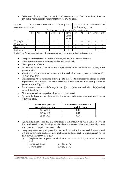
• Determine alignment and inclination of generator axis first in vertical, then inhorizontal plane. Record measurement in following table.Site of Clearance b between half-coupling ends, Distances a to generatrices ofmeasurements mmhalf-couplings, mmPositions of rotating parts of generating set0 0 90 0 180 0 270 0 360 0 Mean 0 0 90 0 180 0 270 0 360 0ClearanceTop a 1 ;b 1 + + + + + + + – – – +Bottom a 3 ;b 3 + + + + + + – – + – –Right a 2 ;b 2 + + + + + + – + – – –Left a 4 ;b 4 + + + + + + – – – + –Note: The “plus” sign indicates that measurements were carried out at this point.• Compute displacements of generator rotor, <strong>for</strong> ensuring correct position• Move generator rotor in correct position and check axis.• Check position of stator• All measurements of clearances and displacement should be recorded viewing fromgenerator side.• Magnitude ‘a’ are measured in one position and after turning rotating parts by 90 o ,180 o , 270 o & 360 o• End clearance ‘b’ is measured at four points in order to eliminate the effects of axialdisplacement of the rotor. The mean clearance is then calculated <strong>for</strong> each position ofgenerator rotor (Fig 13)• The measurements are satisfactory if both [(a 1 + a 3 )-(a 2 +a 4 )] and [(b 1 + b 3 )-(b 2 +b 4 )]are with in 0.02 mm.• All measurements are repeated till good set is achieved.• Permissible deviations in alignment of horizontal <strong>hydro</strong> generating unit are given infollowing table.Rotational speed ofgenerating set, rpmPermissible skewness andeccentricity, mmUp to 500 0.15Up to 750 0.10Up to 1500 0.08• If, after alignment radial and end clearances at diametrically opposite point are with inlimit as shown in table, the alignment is taken as adequate other wise repeat alignmentprocedure and compute more accurately.• Computing eccentricity of generator shaft with respect to turbine shaft (measurement‘a’) and its direction and computing inclination and its direction (measurement ‘b’) isdone as explained below: (Fig 14)(i) Displacement of generator shaft axis due to eccentricity relative to turbineshaft:Horizontal plane h x = (a 2 -a 4 ) / 2Vertical plane h y = (a 1 -a 3 ) / 2<strong>AHEC</strong>/MNRE/SHP Standards/ E&M Works – Guidelines <strong>for</strong> Operation and Maintenance of Small Hydropower Station 71