standards / manuals / guidelines for small hydro development - AHEC
standards / manuals / guidelines for small hydro development - AHEC
standards / manuals / guidelines for small hydro development - AHEC

Create successful ePaper yourself
Turn your PDF publications into a flip-book with our unique Google optimized e-Paper software.
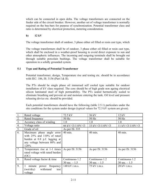
which can be connected in open delta. The voltage trans<strong>for</strong>mers are connected on thefeeder side of the circuit breaker. However, another set of voltage trans<strong>for</strong>mer is normallyrequired on the bus-bars <strong>for</strong> purpose of synchronization. Potential trans<strong>for</strong>mer class andratio is determined by electrical protection, metering consideration.b) 12 kVThe voltage trans<strong>for</strong>mer shall of outdoor, 3 phase either oil filled or resin cast type, whichThe voltage trans<strong>for</strong>mers shall be of outdoor, 3 phase either oil filled or resin cast type,which shall be enclosed in a weather-proof housing to avoid direct exposure to sun andother atmospheric influences. The incoming and outgoing terminals shall be brought outthrough suitable porcelain bushings. The voltage trans<strong>for</strong>mer shall be suitable <strong>for</strong>operation in a solidly grounded system.5.1 Type and Rating of Potential Trans<strong>for</strong>merPotential trans<strong>for</strong>mer, design, Temperature rise and testing etc. should be in accordancewith IEC: 186, IS: 3156 (Part I & II).The PTs should be single phase oil immersed self cooled type suitable <strong>for</strong> outdoorinstallation of kV class required. The core should be of high grade non ageing electricalsilicon laminated steel of high permeability. The PTs sealed hermetically scaled toeliminate breathing and prevent air and moisture entering the tank. Oil level and pressurereleasing device etc. should be provided.Each potential trans<strong>for</strong>mers should have the following (table 2.5.1) particulars under thesite conditions <strong>for</strong> the system under design (typical values <strong>for</strong> 72.5 kV system are given).1. Rated voltage 72.5 kV 36 kV 12 kV2. Rated frequency 50 Hz 50 Hz 50 Hz3. Accuracy class of winding 1.0 1.0 1.04. Voltage ratio 66 kV/3/110V/3 33 kV/3/110V/3 11 kV/3/110V/35. Grade of oil As per IS: 3356. Maximum phase angle error 40 min. 40 min. 40 min.with 25% and 110% of ratedburden at 0.8 p.f. lagging atany voltage between 80% and120%7. Temperature rise at 1-1 times As per IS: 3156 As per IS: 3156 As per IS: 3156rated voltage with rated burden(OC)8. Rated voltage factor & time Continuous 1.2 Continuous 1.2 Continuous 1.29. 1 minute power frequency(wet/dry) withstand testvoltage30 sec. – 1.5 30 sec. – 1.5 30 sec. – 1.5140 kV r.m.s. 75 kV r.m.s. 28 kV r.m.s.2-11