- Page 2 and 3:
Practical Modern SCADA Protocols: D
- Page 4 and 5:
Practical Modern SCADA Protocols: D
- Page 6 and 7:
Contents Preface ..................
- Page 8 and 9:
Contents vii 12.6 Frame reception .
- Page 10 and 11:
Preface ix Chapter 3: Open SCADA pr
- Page 12 and 13:
1 Introduction Objectives When you
- Page 14 and 15:
Introduction 3 Figure 1.2 PC to IED
- Page 16 and 17:
Introduction 5 The interconnection
- Page 18 and 19:
Introduction 7 a number of sub-path
- Page 20 and 21:
Introduction 9 The Internet protoco
- Page 22 and 23:
Introduction 11 Outside the utiliti
- Page 24 and 25:
Fundamentals of SCADA communication
- Page 26 and 27:
Fundamentals of SCADA communication
- Page 28 and 29:
Key features of SCADA software incl
- Page 30 and 31:
Fundamentals of SCADA communication
- Page 32 and 33:
2.2.2 Control processor unit (or CP
- Page 34 and 35:
Fundamentals of SCADA communication
- Page 36 and 37:
Fundamentals of SCADA communication
- Page 38 and 39:
Fundamentals of SCADA communication
- Page 40 and 41:
2.5.2 Multi-point architecture (Mul
- Page 42 and 43:
2.6 Communication philosophies Fund
- Page 44 and 45:
Fundamentals of SCADA communication
- Page 46 and 47:
Fundamentals of SCADA communication
- Page 48 and 49:
Fundamentals of SCADA communication
- Page 50 and 51:
Pin 8 - Data carrier detect (DCD) F
- Page 52 and 53:
2.7.6 Synchronous communications 2.
- Page 54 and 55:
The two most common modes of operat
- Page 56 and 57:
2.8.3 Error control/flow control Fu
- Page 58 and 59:
Fundamentals of SCADA communication
- Page 60 and 61:
Fundamentals of SCADA communication
- Page 62 and 63:
Fundamentals of SCADA communication
- Page 64 and 65:
Fundamentals of SCADA communication
- Page 66 and 67:
Fundamentals of SCADA communication
- Page 68 and 69:
Fundamentals of SCADA communication
- Page 70 and 71:
Fundamentals of SCADA communication
- Page 72 and 73:
Fundamentals of SCADA communication
- Page 74 and 75:
3 Open SCADA protocols DNP3 and IEC
- Page 76 and 77:
3.2.2 DNP 3.0 and IEC 60870 protoco
- Page 78 and 79:
4.2 Interoperability and open stand
- Page 80 and 81:
Preview of DNP3 69 The DNP3 User Gr
- Page 82 and 83:
Preview of DNP3 71 The capability t
- Page 84 and 85:
5 Fundamentals of distributed netwo
- Page 86 and 87:
Fundamentals of distributed network
- Page 88 and 89:
Fundamentals of distributed network
- Page 90 and 91:
Fundamentals of distributed network
- Page 92 and 93:
Fundamentals of distributed network
- Page 94 and 95:
5.3.6 Full-duplex procedures Fundam
- Page 96 and 97:
Fundamentals of distributed network
- Page 98 and 99:
Fundamentals of distributed network
- Page 100 and 101:
Fundamentals of distributed network
- Page 102 and 103:
Fundamentals of distributed network
- Page 104 and 105:
Fundamentals of distributed network
- Page 106 and 107:
Fundamentals of distributed network
- Page 108 and 109:
Fundamentals of distributed network
- Page 110 and 111:
Fundamentals of distributed network
- Page 112 and 113:
The message sequences are shown in
- Page 114 and 115:
Fundamentals of distributed network
- Page 116 and 117:
Fundamentals of distributed network
- Page 118 and 119:
Fundamentals of distributed network
- Page 120 and 121:
These rules are illustrated in the
- Page 122 and 123:
Fundamentals of distributed network
- Page 124 and 125:
Fundamentals of distributed network
- Page 126 and 127:
Freeze functions are typically used
- Page 128 and 129:
Fundamentals of distributed network
- Page 130 and 131:
Fundamentals of distributed network
- Page 132 and 133:
Fundamentals of distributed network
- Page 134 and 135:
Fundamentals of distributed network
- Page 136 and 137:
Fundamentals of distributed network
- Page 138 and 139:
Fundamentals of distributed network
- Page 140 and 141:
Fundamentals of distributed network
- Page 142 and 143:
Fundamentals of distributed network
- Page 144 and 145:
Fundamentals of distributed network
- Page 146 and 147:
Fundamentals of distributed network
- Page 148 and 149:
Fundamentals of distributed network
- Page 150 and 151:
Fundamentals of distributed network
- Page 152 and 153:
Fundamentals of distributed network
- Page 154 and 155:
6 Advanced considerations of distri
- Page 156 and 157:
Advanced considerations of distribu
- Page 158 and 159:
Advanced considerations of distribu
- Page 161:
Advanced considerations of distribu
- Page 165:
Advanced considerations of distribu
- Page 169 and 170:
6.2 Interoperability between DNP3 d
- Page 171 and 172:
6.3.2 Data classes and events Advan
- Page 173 and 174:
Recommendations: 6.3.9 Multiple obj
- Page 175 and 176:
6.3.15 Time-tagged binary input eve
- Page 177 and 178:
Advanced considerations of distribu
- Page 179 and 180:
Advanced considerations of distribu
- Page 181 and 182:
Advanced considerations of distribu
- Page 183 and 184:
Advanced considerations of distribu
- Page 185 and 186:
Advanced considerations of distribu
- Page 187 and 188:
Preview of IEC 60870-5 171 7.2 Stan
- Page 189 and 190:
Preview of IEC 60870-5 173 Under IE
- Page 191 and 192:
Preview of IEC 60870-5 175 over cor
- Page 193 and 194:
8 Fundamentals of IEC 60870-5 8.1 T
- Page 195 and 196:
Fundamentals of IEC 60870-5 179 8.1
- Page 197 and 198:
8.1.9 IEC 60870-5-101 1995 Fundamen
- Page 199 and 200:
Fundamentals of IEC 60870-5 183 pro
- Page 201 and 202:
Fundamentals of IEC 60870-5 185 MAS
- Page 203 and 204:
8.4 Data link layer Fundamentals of
- Page 205 and 206:
8.4.2 Order of information Fundamen
- Page 207 and 208:
8.4.5 Unbalanced and balanced trans
- Page 209 and 210:
Fundamentals of IEC 60870-5 193 Sta
- Page 211 and 212:
Station/link initialization, balanc
- Page 213 and 214:
Fundamentals of IEC 60870-5 197 The
- Page 215 and 216:
Fundamentals of IEC 60870-5 199 To
- Page 217 and 218:
Function codes from secondary stati
- Page 219 and 220:
Fundamentals of IEC 60870-5 203 is
- Page 221 and 222:
The following notes apply to these
- Page 223 and 224:
Fundamentals of IEC 60870-5 207 Typ
- Page 225 and 226:
Fundamentals of IEC 60870-5 209 Typ
- Page 227 and 228:
Fundamentals of IEC 60870-5 211 Whe
- Page 229 and 230:
Fundamentals of IEC 60870-5 213 8.5
- Page 231 and 232:
Fundamentals of IEC 60870-5 215 to
- Page 233 and 234:
Fundamentals of IEC 60870-5 217 Mas
- Page 235 and 236:
Fundamentals of IEC 60870-5 219 Qua
- Page 237 and 238:
Fundamentals of IEC 60870-5 221 Key
- Page 239 and 240:
Fundamentals of IEC 60870-5 223 SVA
- Page 241 and 242:
Fundamentals of IEC 60870-5 225 Key
- Page 243 and 244:
Fundamentals of IEC 60870-5 227 DCO
- Page 245 and 246:
8.6.4 Qualifier information element
- Page 247 and 248:
Key - QOC Qualifier of command QU Q
- Page 249 and 250:
Fundamentals of IEC 60870-5 233 SCQ
- Page 251 and 252:
Fundamentals of IEC 60870-5 235 LOF
- Page 253 and 254:
Fundamentals of IEC 60870-5 237 FBP
- Page 255 and 256:
Fundamentals of IEC 60870-5 239 In
- Page 257 and 258:
Fundamentals of IEC 60870-5 241 Typ
- Page 259 and 260:
Fundamentals of IEC 60870-5 243 Typ
- Page 261 and 262:
Fundamentals of IEC 60870-5 245 Typ
- Page 263 and 264:
Fundamentals of IEC 60870-5 247 Val
- Page 265 and 266:
Type 11 Measured, scaled value Fund
- Page 267 and 268:
Fundamentals of IEC 60870-5 251 Typ
- Page 269 and 270:
Fundamentals of IEC 60870-5 253 Typ
- Page 271 and 272:
Fundamentals of IEC 60870-5 255 Val
- Page 273 and 274:
Type 20 Packed single-point with st
- Page 275 and 276:
Fundamentals of IEC 60870-5 259 Pro
- Page 277 and 278:
Fundamentals of IEC 60870-5 261 Typ
- Page 279 and 280:
Fundamentals of IEC 60870-5 263 Typ
- Page 281 and 282:
Fundamentals of IEC 60870-5 265 Typ
- Page 283 and 284:
Fundamentals of IEC 60870-5 267 8.7
- Page 285 and 286:
Fundamentals of IEC 60870-5 269 Typ
- Page 287 and 288:
Fundamentals of IEC 60870-5 271 Typ
- Page 289 and 290:
Fundamentals of IEC 60870-5 273 Typ
- Page 291 and 292:
Fundamentals of IEC 60870-5 275 Typ
- Page 293 and 294:
Fundamentals of IEC 60870-5 277 Typ
- Page 295 and 296:
Fundamentals of IEC 60870-5 279 Typ
- Page 297 and 298:
Fundamentals of IEC 60870-5 281 Typ
- Page 299 and 300:
Fundamentals of IEC 60870-5 283 Typ
- Page 301 and 302:
Fundamentals of IEC 60870-5 285 Val
- Page 303 and 304:
9.1.1 Station initialization Advanc
- Page 305 and 306:
9.1.2 Data acquisition Advanced con
- Page 307 and 308:
Advanced considerations of IEC 6087
- Page 309 and 310:
Advanced considerations of IEC 6087
- Page 311 and 312:
In Figure 9.4 the following time sy
- Page 313 and 314:
Advanced considerations of IEC 6087
- Page 315 and 316:
Basic application functions: 9.2.3
- Page 317 and 318:
Advanced considerations of IEC 6087
- Page 319 and 320:
Advanced considerations of IEC 6087
- Page 321 and 322:
Advanced considerations of IEC 6087
- Page 323 and 324:
10 Differences between DNP3 and IEC
- Page 325 and 326: Data objects: Differences between D
- Page 327 and 328: 10.2 Which one will win? Difference
- Page 329 and 330: Intelligent electronic devices (IED
- Page 331 and 332: 11.2.5 Communications Intelligent e
- Page 333 and 334: Ethernet and TCP/IP networks 317 tr
- Page 335 and 336: Ethernet and TCP/IP networks 319 Th
- Page 337 and 338: Ethernet and TCP/IP networks 321 Fi
- Page 339 and 340: 12.2.5 10Broad36 12.2.6 1Base5 Ethe
- Page 341 and 342: Ethernet and TCP/IP networks 325 si
- Page 343 and 344: Ethernet and TCP/IP networks 327 As
- Page 345 and 346: 12.8.4 Length Ethernet and TCP/IP n
- Page 347 and 348: Ethernet and TCP/IP networks 331 To
- Page 349 and 350: 12.11.8 Fast Ethernet Ethernet and
- Page 351 and 352: 12.12 TCP/IP Ethernet and TCP/IP ne
- Page 353 and 354: Ethernet and TCP/IP networks 337
- Page 355 and 356: Ethernet and TCP/IP networks 339 Fi
- Page 357 and 358: Here follows a brief description of
- Page 359 and 360: Unicast addresses Ethernet and TCP/
- Page 361 and 362: The three common fields are: Ethern
- Page 363 and 364: Ethernet and TCP/IP networks 347 Th
- Page 365 and 366: 13 Fieldbus and SCADA communication
- Page 367 and 368: Fieldbus and SCADA communications s
- Page 369 and 370: Fieldbus and SCADA communications s
- Page 371 and 372: • Programmable logic controllers
- Page 373 and 374: Fieldbus and SCADA communications s
- Page 375: Three such ‘services’ are readi
- Page 379 and 380: 14.2 UCA development UCA protocol 3
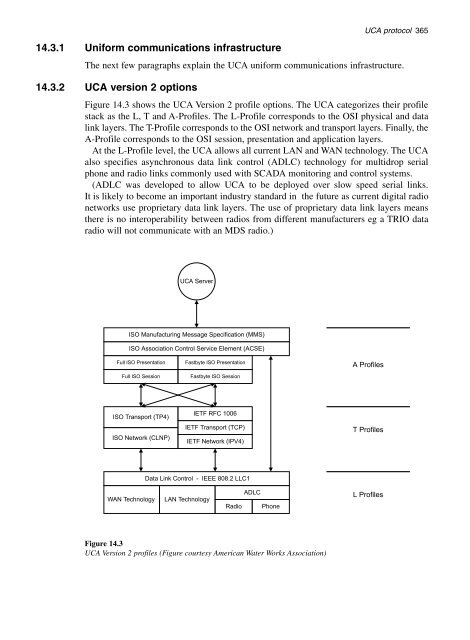
- Page 381 and 382: 14.3.1 Uniform communications infra
- Page 383 and 384: UCA protocol 367 14.3.4 Uniform app
- Page 385 and 386: 14.3.5 Uniform data model UCA proto
- Page 387 and 388: Figure 14.6 Device object model ove
- Page 389 and 390: UCA protocol 373 An excellent refer
- Page 391 and 392: Applications of DNP3 and SCADA prot
- Page 393 and 394: Applications of DNP3 and SCADA prot
- Page 395 and 396: Applications of DNP3 and SCADA prot
- Page 397 and 398: PDS 500 Data Map Applications of DN
- Page 399 and 400: Applications of DNP3 and SCADA prot
- Page 401 and 402: Applications of DNP3 and SCADA prot
- Page 403 and 404: Applications of DNP3 and SCADA prot
- Page 405 and 406: Applications of DNP3 and SCADA prot
- Page 407 and 408: 16 Future developments Objectives W
- Page 409 and 410: Appendix A Glossary 3GPP 10Base2 10
- Page 411 and 412: Appendix A: Glossary 395 ATM Attenu
- Page 413 and 414: Appendix A: Glossary 397 Capacitanc
- Page 415 and 416: Appendix A: Glossary 399 Decibel (d
- Page 417 and 418: Appendix A: Glossary 401 ESS Etherl
- Page 419 and 420: Appendix A: Glossary 403 I/O addres
- Page 421 and 422: Manchester encoding Appendix A: Glo
- Page 423 and 424: Appendix A: Glossary 407 Packet PAD
- Page 425 and 426: Appendix A: Glossary 409 RFI Ring R
- Page 427 and 428:
Appendix A: Glossary 411 TDMA TDR T
- Page 429 and 430:
Appendix A: Glossary 413 X.25 CCITT
- Page 431 and 432:
Appendix B: Implementers of DNP3 41
- Page 433 and 434:
Appendix B: Implementers of DNP3 41
- Page 435 and 436:
DNP3 device profile Appendix C: Sam
- Page 437 and 438:
Appendix C: Sample device profile d
- Page 439 and 440:
Appendix C: Sample device profile d
- Page 441 and 442:
Appendix C: Sample device profile d
- Page 443 and 444:
Appendix C: Sample device profile d
- Page 445 and 446:
Software setup Appendix D: Practica
- Page 447 and 448:
Appendix D: Practicals 431 1. Set u
- Page 449 and 450:
Objectives • To show how a basic
- Page 451 and 452:
Implementation/setting up TCP/IP Cl
- Page 453 and 454:
Appendix D: Practicals 437 Click on
- Page 455 and 456:
Appendix D: Practicals 439 Click on
- Page 457 and 458:
Appendix D: Practicals 441 Now rese
- Page 459 and 460:
Appendix D: Practicals 443 Practica
- Page 461 and 462:
Appendix D: Practicals 445 This sho
- Page 463 and 464:
Appendix D: Practicals 447 Once you
- Page 465 and 466:
IMPORTANT NOTICE: Appendix D: Pract
- Page 467 and 468:
Appendix D: Practicals 451 (This is
- Page 469 and 470:
Appendix D: Practicals 453 PRACTICA
- Page 471 and 472:
Click on the Diags button and the f
- Page 473 and 474:
Appendix D: Practicals 457 The scre
- Page 475 and 476:
Appendix D: Practicals 459 Assume t
- Page 477 and 478:
Appendix D: Practicals 461 Problem
- Page 479 and 480:
Network Loading Assumptions Item Da
- Page 481 and 482:
2. IEC 60870-5-101 Packet Analysis
- Page 483 and 484:
3.1.1.1.1 Appendix D: Practicals 46
- Page 485 and 486:
Appendix D: Practicals 469 Valid Ca
- Page 487 and 488:
3.1.1.1.7 Type 14 INFORMATION OBJEC
- Page 489 and 490:
Appendix D: Practicals 473 3.1.1.1.
- Page 491 and 492:
Appendix D: Practicals 475 QDS Qual
- Page 493 and 494:
Appendix D: Practicals 477 7 6 5 4
- Page 495 and 496:
3.1.1.1.11 Communication 1 Appendix
- Page 497 and 498:
Communication 1 Answer Appendix D:
- Page 499 and 500:
CITECT PRACTICAL For Citect Version
- Page 501 and 502:
Appendix D: Practicals 485 Next cli
- Page 503 and 504:
Appendix D: Practicals 487 (3) Defi
- Page 505 and 506:
Appendix D: Practicals 489
- Page 507 and 508:
Appendix D: Practicals 491 (4) Crea
- Page 509 and 510:
Appendix D: Practicals 493 Use the
- Page 511 and 512:
Appendix D: Practicals 495 Click on
- Page 513 and 514:
Appendix D: Practicals 497 When fin
- Page 515 and 516:
Appendix D: Practicals 499 What is
- Page 517 and 518:
Communication 2 05640DC405001A00637
- Page 519 and 520:
05640DC405001A006378C6C601010200003
- Page 521 and 522:
Appendix D: Practicals 505 What are
- Page 523 and 524:
Appendix D: Practicals 507 01 01 01
- Page 525 and 526:
Appendix D: Practicals 509 E2 81 00
- Page 527 and 528:
Appendix D: Practicals 511 At fist
- Page 529 and 530:
Appendix D: Practicals 513 Then rem
- Page 531 and 532:
Appendix D: Practicals 515 The next
- Page 533 and 534:
Packet Interpretation Practical App
- Page 535 and 536:
056408C40300A200EA80C5C5171E4405641
- Page 537 and 538:
Appendix D: Practicals 521 Communic
- Page 539 and 540:
05640DC405001A006378C6C601010200003
- Page 541 and 542:
Appendix D: Practicals 525 What is
- Page 543 and 544:
01 01 01 01 01 01 01 crc:BB crc:C3
- Page 545 and 546:
Appendix D: Practicals 529 Read Dat
- Page 547 and 548:
Index 531 Carrier sense with multip
- Page 549 and 550:
Index 533 support for protocol, 310
- Page 551 and 552:
Index 535 process related, 220 bina
- Page 553:
Index 537 signal quality detector,