- Page 2 and 3:
The Art of the Helicopter
- Page 4 and 5:
The Art of the Helicopter John Watk
- Page 6 and 7:
Contents Preface xi Acknowledgement
- Page 8 and 9:
4.12 Feathering 134 4.13 Pitch cont
- Page 10:
8.5 Power management 326 8.6 Flying
- Page 13 and 14:
xii Preface reader to make sense of
- Page 16 and 17:
1 Introduction to rotorcraft 1.1 Ap
- Page 18 and 19:
Introduction to rotorcraft 3 Fig. 1
- Page 20 and 21:
Introduction to rotorcraft 5 Fig. 1
- Page 22 and 23:
Introduction to rotorcraft 7 Fig. 1
- Page 24 and 25:
Introduction to rotorcraft 9 for th
- Page 26 and 27:
Introduction to rotorcraft 11 Fig.
- Page 28 and 29:
(a) (b) (c) (d) Introduction to rot
- Page 30 and 31:
Fig. 1.18 The contra-rotating coaxi
- Page 32 and 33:
Fig. 1.20 The structure of a light
- Page 34 and 35:
Introduction to rotorcraft 19 wings
- Page 36 and 37:
Introduction to rotorcraft 21 a rot
- Page 38 and 39:
Technical background 23 Fig. 2.1 At
- Page 40 and 41:
Fig. 2.3 Effect of force on velocit
- Page 42 and 43:
C Force A E Resultant (a) Force B (
- Page 44 and 45:
(a) (b) Technical background 29 Fig
- Page 46 and 47:
Technical background 31 Fig. 2.11 A
- Page 48 and 49:
Technical background 33 Fig. 2.12 (
- Page 50 and 51:
Technical background 35 If the volu
- Page 52 and 53:
Fig. 2.16 The definition of a radia
- Page 54 and 55:
Technical background 39 force would
- Page 56 and 57:
Technical background 41 Figure 2.20
- Page 58 and 59:
Technical background 43 force where
- Page 60 and 61:
Technical background 45 the cosine
- Page 62 and 63:
Technical background 47 Fig. 2.28 F
- Page 64 and 65:
Technical background 49 Fig. 2.30 T
- Page 66 and 67:
Technical background 51 centripetal
- Page 68 and 69:
2.17 The gyroscope Technical backgr
- Page 70 and 71:
Technical background 55 of oscillat
- Page 72 and 73:
Technical background 57 the inertia
- Page 74 and 75:
Technical background 59 shut down a
- Page 76 and 77:
3 Introduction to helicopter dynami
- Page 78 and 79:
Introduction to helicopter dynamics
- Page 80 and 81:
Introduction to helicopter dynamics
- Page 82 and 83:
Introduction to helicopter dynamics
- Page 84 and 85:
Introduction to helicopter dynamics
- Page 86 and 87:
Introduction to helicopter dynamics
- Page 88 and 89: Introduction to helicopter dynamics
- Page 90 and 91: Introduction to helicopter dynamics
- Page 92 and 93: Introduction to helicopter dynamics
- Page 94 and 95: Introduction to helicopter dynamics
- Page 96 and 97: Introduction to helicopter dynamics
- Page 98 and 99: Introduction to helicopter dynamics
- Page 100 and 101: (a) (c) (b) Introduction to helicop
- Page 102 and 103: Introduction to helicopter dynamics
- Page 104 and 105: (a) (b) (c) (d) Introduction to hel
- Page 106 and 107: Fig. 3.23 Conditions for hover and
- Page 108 and 109: Introduction to helicopter dynamics
- Page 110 and 111: (a) (b) Introduction to helicopter
- Page 112 and 113: Introduction to helicopter dynamics
- Page 114 and 115: Introduction to helicopter dynamics
- Page 116 and 117: (a) (b) Introduction to helicopter
- Page 118 and 119: Introduction to helicopter dynamics
- Page 120 and 121: Introduction to helicopter dynamics
- Page 122 and 123: Introduction to helicopter dynamics
- Page 124 and 125: Introduction to helicopter dynamics
- Page 126 and 127: Introduction to helicopter dynamics
- Page 128 and 129: Introduction to helicopter dynamics
- Page 130 and 131: Introduction to helicopter dynamics
- Page 132 and 133: 4.1 Introduction 4 Rotors in practi
- Page 134 and 135: (a) (b) Rotors in practice 119 Fig.
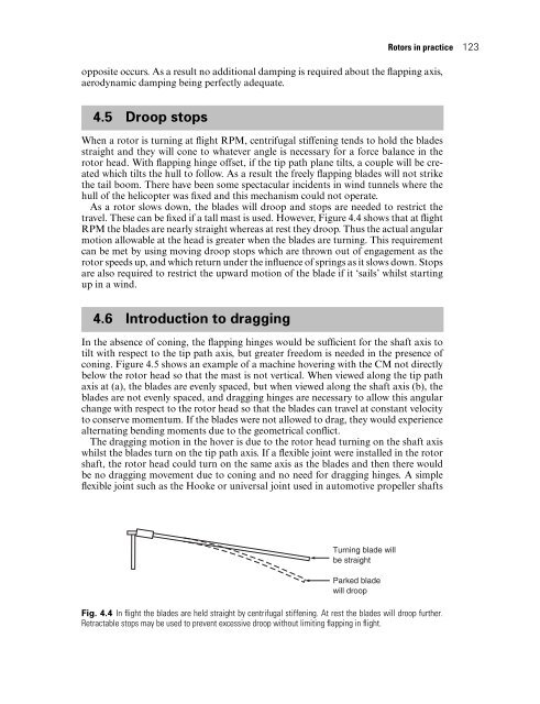
- Page 136 and 137: Rotors in practice 121 Designers of
- Page 140 and 141: Rotors in practice 125 Fig. 4.6 (a)
- Page 142 and 143: Rotors in practice 127 assembly tha
- Page 144 and 145: Rotors in practice 129 Pitch change
- Page 146 and 147: × T=c× D Rotors in practice 131 F
- Page 148 and 149: Rotors in practice 133 In a real he
- Page 150 and 151: Rotors in practice 135 Fig. 4.15 Va
- Page 152 and 153: (a) (b) Rotors in practice 137 Fig.
- Page 154 and 155: Rotors in practice 139 Fig. 4.18 Th
- Page 156 and 157: Rotors in practice 141 swashplate a
- Page 158 and 159: Fig. 4.23 A fixed-pitch tilting hea
- Page 160 and 161: Rotors in practice 145 Fig. 4.25 Bl
- Page 162 and 163: Rotors in practice 147 Fig. 4.27 Ef
- Page 164 and 165: Rotors in practice 149 Fig. 4.29 (a
- Page 166 and 167: Rotors in practice 151 concerned ar
- Page 168 and 169: Rotors in practice 153 and lag damp
- Page 170 and 171: Rotors in practice 155 disappears a
- Page 172 and 173: (d) (e) (f) Rotors in practice 157
- Page 174 and 175: Rotors in practice 159 hull and a v
- Page 176 and 177: Rotors in practice 161 Fig. 4.35 (C
- Page 178 and 179: Rotors in practice 163 Abrasion is
- Page 180 and 181: Rotors in practice 165 There are so
- Page 182 and 183: eing more visible to ground personn
- Page 184 and 185: otates the rod in the screw thread.
- Page 186 and 187: In the case of a rotor having offse
- Page 188 and 189:
The tail rotor designer is faced wi
- Page 190 and 191:
Fig. 5.5 A right-side wrong-directi
- Page 192 and 193:
centre of mass. The solution was to
- Page 194 and 195:
safe to start the rotors. However,
- Page 196 and 197:
Fig. 5.10 Tail plane locations: (a)
- Page 198 and 199:
Fig. 5.12 (a) A top-mounted fin is
- Page 200 and 201:
Fig. 5.14 (a) Main rotor lateral ro
- Page 202 and 203:
long. The cross-section of the duct
- Page 204 and 205:
drag. However, the slots are emitti
- Page 206 and 207:
6 Engines and transmissions The pow
- Page 208 and 209:
Engines and transmissions 193 the D
- Page 210 and 211:
(a) (b) Engines and transmissions 1
- Page 212 and 213:
(a) (b) (c) Engines and transmissio
- Page 214 and 215:
Fig. 6.5 A typical horizontally opp
- Page 216 and 217:
Engines and transmissions 201 the v
- Page 218 and 219:
Engines and transmissions 203 The c
- Page 220 and 221:
6.9 The oil system Engines and tran
- Page 222 and 223:
Engines and transmissions 207 (non-
- Page 224 and 225:
(a) (b) Engines and transmissions 2
- Page 226 and 227:
Engines and transmissions 211 a hot
- Page 228 and 229:
Engines and transmissions 213 Fig.
- Page 230 and 231:
Engines and transmissions 215 In wa
- Page 232 and 233:
Engines and transmissions 217 is a
- Page 234 and 235:
Engines and transmissions 219 Fig.
- Page 236 and 237:
Engines and transmissions 221 own t
- Page 238 and 239:
Fig. 6.16 The complex fuel system o
- Page 240 and 241:
Engines and transmissions 225 Fig.
- Page 242 and 243:
Engines and transmissions 227 Fig.
- Page 244 and 245:
Engines and transmissions 229 Fig.
- Page 246 and 247:
Engines and transmissions 231 Fig.
- Page 248 and 249:
Engines and transmissions 233 and c
- Page 250 and 251:
Engines and transmissions 235 Fig.
- Page 252 and 253:
Engines and transmissions 237 Sensi
- Page 254 and 255:
Engines and transmissions 239 Fig.
- Page 256 and 257:
Engines and transmissions 241 Fig.
- Page 258 and 259:
Engines and transmissions 243 the A
- Page 260 and 261:
Engines and transmissions 245 Fig.
- Page 262 and 263:
Fig. 6.37 Displays which may be see
- Page 264 and 265:
Engines and transmissions 249 Fig.
- Page 266 and 267:
Engines and transmissions 251 slipr
- Page 268 and 269:
Engines and transmissions 253 a fau
- Page 270 and 271:
Engines and transmissions 255 resul
- Page 272 and 273:
Engines and transmissions 257 The p
- Page 274 and 275:
Fig. 7.1 (a) A minimal control loop
- Page 276 and 277:
Fig. 7.2 (a) When attitude conditio
- Page 278 and 279:
fixed point in the hover despite ex
- Page 280 and 281:
(a) (b) Fig. 7.4 (a) The earth beha
- Page 282 and 283:
7.4 Compass errors A magnetic compa
- Page 284 and 285:
In most cases the machine will have
- Page 286 and 287:
Fig. 7.7 The remote indicator for a
- Page 288 and 289:
is set by the use of a control knob
- Page 290 and 291:
Fig. 7.11 The VSI (vertical speed i
- Page 292 and 293:
Fig. 7.13 A chaser system which all
- Page 294 and 295:
e modified if the gyro is in a movi
- Page 296 and 297:
must be in steady flight when the D
- Page 298 and 299:
arranged on opposite sides of the p
- Page 300 and 301:
Fig. 7.19 The turn indicator is spr
- Page 302 and 303:
7.17 Airflow-sensing devices The he
- Page 304 and 305:
Fig. 7.24 Using RADAR signals. At (
- Page 306 and 307:
Fig. 7.27 Transducers used in signa
- Page 308 and 309:
Fig. 7.28 In PCM or digital signall
- Page 310 and 311:
(a) Fig. 7.30 Using slicing and rec
- Page 312 and 313:
Fig. 7.33 The false codes created i
- Page 314 and 315:
Fig. 7.35 In a pure binary system,
- Page 316 and 317:
Fig. 7.38 Producing two’s complem
- Page 318 and 319:
Fig. 7.40 A power-assisted hydrauli
- Page 320 and 321:
Fig. 7.42 An electro-hydraulic valv
- Page 322 and 323:
path axis and the flybar axis diver
- Page 324 and 325:
and autostabilization, it also prov
- Page 326 and 327:
Fig. 7.47 The Lockheed gyrobar syst
- Page 328 and 329:
Fig. 7.49 In the Lockheed AMCS, the
- Page 330 and 331:
Fig. 7.50 With the autopilot diseng
- Page 332 and 333:
or without the AFCS. Systems of thi
- Page 334 and 335:
Thus if a VOR receiver detected a 9
- Page 336 and 337:
7.29 Fault tolerance In feedback sy
- Page 338 and 339:
8 Helicopter performance 8.1 Introd
- Page 340 and 341:
Helicopter performance 325 column i
- Page 342 and 343:
Helicopter performance 327 Fig. 8.1
- Page 344 and 345:
Helicopter performance 329 to skid
- Page 346 and 347:
(a) (b) Helicopter performance 331
- Page 348 and 349:
Helicopter performance 333 Fig. 8.7
- Page 350 and 351:
8.7 Climbingand descending Helicopt
- Page 352 and 353:
Helicopter performance 337 In the c
- Page 354 and 355:
Helicopter performance 339 of its c
- Page 356 and 357:
8.10 Stability Helicopter performan
- Page 358 and 359:
Fig. 8.13 The origin of pitchup ins
- Page 360 and 361:
Helicopter performance 345 moment f
- Page 362 and 363:
9 Other types of rotorcraft Althoug
- Page 364 and 365:
Other types of rotorcraft 349 De la
- Page 366 and 367:
Other types of rotorcraft 351 Fig.
- Page 368 and 369:
Other types of rotorcraft 353 incre
- Page 370 and 371:
Other types of rotorcraft 355 and c
- Page 372 and 373:
Fig. 9.7 The Bell-Boeing Osprey til
- Page 374 and 375:
(a) (b) Other types of rotorcraft 3
- Page 376 and 377:
Other types of rotorcraft 361 Fig.
- Page 378 and 379:
Other types of rotorcraft 363 Fig.
- Page 380 and 381:
Other types of rotorcraft 365 a low
- Page 382 and 383:
Other types of rotorcraft 367 the y
- Page 384 and 385:
Other types of rotorcraft 369 Fig.
- Page 386 and 387:
Other types of rotorcraft 371 the r
- Page 388 and 389:
Other types of rotorcraft 373 For e
- Page 390 and 391:
Other types of rotorcraft 375 Fig.
- Page 392 and 393:
Other types of rotorcraft 377 Fig.
- Page 394 and 395:
Acceleration: and force, 22-5 and v
- Page 396 and 397:
Convertiplane, 11-12, 355-8 Bell-Bo
- Page 398 and 399:
tanks, 219-20 turbine engines, 237-
- Page 400 and 401:
Lockheed flybar system, 309-13 AMCS
- Page 402 and 403:
centrifugal stiffening, 71, 100 and
- Page 404 and 405:
tail/main rotor interaction, 173 te