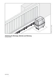
Anleitung für Montage, Betrieb und Wartung Installation ... - Hormann.fr
Anleitung für Montage, Betrieb und Wartung Installation ... - Hormann.fr
Anleitung für Montage, Betrieb und Wartung Installation ... - Hormann.fr

Create successful ePaper yourself
Turn your PDF publications into a flip-book with our unique Google optimized e-Paper software.
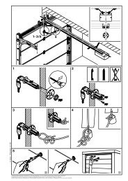
ENGLISH2 INSTALLATION INSTRUCTIONSNoteWhen drilling holes, cover the operator so as to avoid thepenetration of dust and shavings, since these can lead tomalfunctions.2.1 Garage door operator2.2 Required clearance for installing the operatorWhen installing the operator the clearance between thedoor at its highest point of travel and the ceiling must beat least 30 mm (see fig. 1.1a/1.1b). Please checkthese dimensions!2.3 On a sectional door, the mechanical latch must becompletely dismantled (see fig. 1.3a).04.2007 TR10A041-C REATTENTIONWhen installing the operator the pull rope mustbe removed (see fig. 1.2a)2.4 Centrally positioned lock on a sectional doorFor sectional doors with a centrally positioned handle,fit the lintel bracket and the door link bracket off-centre(see fig. 1.5a).2.5 Off-centred reinforcement profile on a sectionaldoorIn the case of an off-centred reinforcement profile on asectional door, fit the door link bracket to the nearestreinforcement profile on the left or right (see fig. 1.5a).NoteFor timber doors, use - contrary to the illustrated section -5 x 35 wood screws <strong>fr</strong>om the pack of screws supplied withthe door (3 mm Ø drill hole).2.6 The mechanical latches on an up-and-over doormust be immobilized (see figs. 1.2b/1.3b/1.4b ). Thelatches for door models not referred to in theseinstructions must be locked in position on site.2.7 NoteFor up-and-over doors with an ornamental wroughtiron door handle - contrary to the illustrated section(see figs. 1.5b/1.6b) - the lintel bracket and the door linkbracket must be attached off-centre.For N80-doors with timber infill, the lower holes in the lintelbracket have to be used for installation (see fig. 1.6b).2.8 BoomATTENTIONDepending on the application, only the boomsrecommended by us may be used for the garagedoor operators (see product information).2.9 Before installing the boomNoteBefore mounting the boom to the lintel or ceiling, push thecarriage in the engaged state (see section 2.11.2) approx.20 cm <strong>fr</strong>om the CLOSE end-of-travel position into the OPENend-of-travel position. It is no longer possible to do this withthe carriage engaged, once the limit stops and the operatorhave been installed (see fig. 2.1).2.10 Installing the boomNoteFor <strong>und</strong>ergro<strong>und</strong> and collective garage operators, the boomhas to be fixed to the ceiling using a second support. Seefigs. 2.4a and 2.5 for mounting.2.11 Boom operating modesThe boom allows two different operating modes:2.11.1 Manual operation (see fig. 4.1)The carriage is disengaged <strong>fr</strong>om the belt lock; i.e. thedoor is not directly connected to the operator enablingthe door to be moved by hand.To disengage the carriage, the rope of the mechanicalrelease must have been pulled.NoteIf on disengagement the carriage is at the CLOSE end-oftravelposition, the rope of the mechanical release must bepulled until the carriage has been moved so far along theboom that it can no longer hook into the limit stop (carriagetravels a distance of approx. 3 cm). To be able to permanentlyoperate the door manually, the rope must be fixedon the carriage as shown in fig. 4.2.ATTENTIONIf in countries in which the European StandardEN 13241-1 must be complied with, the garagedoor operator is retrofitted by a specialist to aHörmann sectional door without springbreakage safety device (BR30), the installerresponsible must also install a retrofit kit to thecarriage. This kit comprises a screw to securethe carriage against inadvertent disengagementand a new pull rope sign, showing how to usethe kit and carriage in the two boom operatingmodes.2.11.2 Automatic operation (see fig. 6)The belt lock is engaged in the carriage, i.e. the doorand the operator are connected to each other, therebyallowing power operation of the door.To prepare the carriage for engagement, the green buttonmust be pressed. The belt must then be moved towardsthe carriage until the belt lock engages into it.ATTENTIONDo not insert fingers into the boom while thedoor is moving ➜ Risk of trapped fingers!2.12 Establishing the end-of-travel positions byinstalling the limit stops1) Insert the limit stop for the OPEN end-of-travel positionloosely into the boom between the carriage and thedrive unit. Push the door by hand into the OPENposition. In doing so, the limit stop is pushed into thecorrect position. Secure the limit stop for the OPENend-of-travel position (see fig. 5.1).NoteIf in the OPEN end-of-travel position the door does notreach the full passage height, the limit stop can be removedso that the integrated limit stop (in the drive unit head) isused.➤61