Anleitung für Montage, Betrieb und Wartung Installation ... - Hormann.fr
Anleitung für Montage, Betrieb und Wartung Installation ... - Hormann.fr
Anleitung für Montage, Betrieb und Wartung Installation ... - Hormann.fr

Create successful ePaper yourself
Turn your PDF publications into a flip-book with our unique Google optimized e-Paper software.
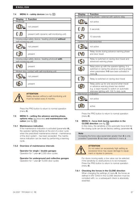
ENGLISH7.4 MENU 4 – safety devices (see fig. 25 )DisplayPhotocellFunctionnot presentpresent (with dynamic self-monitoring unit)Closing edge safety device / leading photocell withoutself-monitoring unitnot presentpresentClosing edge safety device / leading photocell withself-monitoring unitpresentWicket door contact with self-monitoring unitnot presentpresentATTENTIONSafety devices without a self-monitoring unitmust be tested every 6 months.Display FunctionAdvance warning phase / external with options relaynot active5 seconds10 secondsOptions relay (accessories)not activeRelay clocks during advance warning phaseand door travelRelay is switched on during door travel andadvanced warning phaseRelay picks up with the operator lighting. It isswitched on during the advance warning phasewhen parameters 1-5 have been activated inmenu 2.Relay is switched on during door travelRelay picks up for one second when travelor advance warning phase has startede.g. a wipe impulse to switch on automaticstaircase lighting with 100 % duty cycleMaintenance indicationnot activePress the PRG button to return to normal operation(menu 0).7.5 MENU 5 – setting the advance warning phase,options relay (accessories) and maintenance indication(see fig. 26 )7.5.1 Maintenance indicationIf the maintenance indication is activated (parameter A),the operator lighting flashes at the end of a door cyclewhen the prescribed maintenance interval - maintenanceof the door system - has been exceeded. The maintenanceindication can be reset by performing a learningcycle.7.5.2 Overview of maintenance intervalsOperator for single / double garagesOperation for 1 year or 2,000 door cyclesOperator for <strong>und</strong>ergro<strong>und</strong> and collective garagesOperation for 1 year or 10,000 door cyclesactivePress the PRG button to return to normal operation(menu 0).7.6 MENU 6 – force limit during operation in theCLOSE direction (see fig. 27 )In this menu, the sensitivity of the automatic force limit forthe closing cycle can be set (factory setting: parameter 4).NoteIncreasing the force value (parameter greater than 4) is onlypossible if parameter 3 has been selected in menu J.ATTENTIONDo not select an excessively high setting asexcessive force may cause damage to equipmentor injuries to persons.For doors moving easily, a low value can be selectedif the sensitivity to obstructions is to be increased.Press the PRG button to return to normal operation(menu 0).7.6.1 Checking the forces in the CLOSE directionWhen changing the settings of menu 6, the forces asdefined in EN 12453 in the CLOSE direction must becomplied with; i.e. a subsequent check is absolutelyessential.04.2007 TR10A041-C RE67