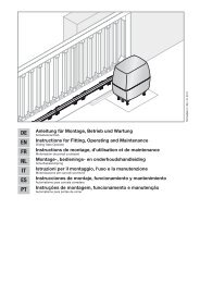
Anleitung für Montage, Betrieb und Wartung Installation ... - Hormann.fr
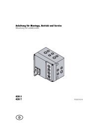
Anleitung für Montage, Betrieb und Wartung Installation ... - Hormann.fr
Anleitung für Montage, Betrieb und Wartung Installation ... - Hormann.fr

You also want an ePaper? Increase the reach of your titles
YUMPU automatically turns print PDFs into web optimized ePapers that Google loves.
ENGLISH4 PUTTING THE OPERATOR INTO SERVICE4.1 General informationThe operator control contains 13 menus, via which theuser can select numerous functions. To put the operatorinto service, however, only two menus are required:adjustment/setting of the door type (menu J) and learningthe distance of travel (menu 1).NoteMenus J, 1, P and 2 are putting into service/function selectionand customer menus; menus 3, 4, 5, 6, 7, 8, 9 and Aare special menus and should be altered only if needed.4.2 Menu selectionMenu selection is made via the PRG button. Here pressingthe button results in changing to the next menu. Onreaching menu P, the system changes back to menu 0.NoteThe menus are released for approx. 60 s, after which thesystem changes back to menu 0.4.3 Putting into serviceOn first-time operation, the control system automaticallyswitches to menu J. After having set the door type,press the PRG button to change to menu 1. On completingthe learning cycles, the system automaticallychanges back to menu 0 (normal operation).4.4 MENU J – adjustment / setting of the door type(see fig. 19 )NoteMenu J can only be accessed on first-time operation orafter restoring the factory settings (see section 4.6/fig. 32 ).In this menu, the operator is optimally adjusted to thecorresponding door. To be able to alter a parameter,press the PRG button until the display flashes rapidly. Bypressing the OPEN button () or the CLOSE button ()you can page through the menu. To be able to alter theparameter, first select the parameter to be changed. Thenpress the PRG button until the decimal point flashes inaddition.Display Operator on Active settingsMenu 7 Menu 9Sectional door 1, 2, 5 1, 3, 5, 904.2007 TR10A041-C REUp-and-over door 0, 2, 5 1, 3, 5, 8(door swinging opentowards outside)Retractable up-and- 1, 2, 5 0, 3, 6, 9over door (doorswinging opentowards inside)Side sectional door, 1, 2, 5 1, 3, 5,... 8, ANoteFor side-hinged doors (with two leaves) parameter "3"should be set. If the door speeds need to be reduced, thenthe corresponding settings should be made in menus 7 and 9.4.5 MENU 1 – learning cycle / programming theoperatorSelect menu 1 by pressing the PRG button. In this menuthe operator can be tuned to the door. In the process, thedistance of travel as well as the required force to openand close the door are learned and automatically stored.4.5.1 Programming the travel limits and the attachedsafety devices (see fig. 20 )NoteThe safety devices must be mounted and connected beforethe operator is programmed.If further safety devices are connected at a later date, thenthe operator must be programmed to learn these. Thisrequires that a new learning cycle is carried out or the correspondingparameter must be set manually in menu 4.Before starting the first learning cycle in the CLOSEdirection, check whether one or more safety devices areconnected. If so, the corresponding menu (menu 4) isautomatically selected.NoteThe carriage must be engaged (see fig. 6) and theremust be no obstructions in the functional area of the safetydevices!If necessary, switch the control system to the learningmode by pressing the PRG button to change to menu 1.Now, a flashing L is displayed after the 1:- First press the OPEN () button. The door travels tothe OPEN end-of-travel position.- Then press the CLOSE () button. The door travelsto the CLOSE end-of-travel position. Now, the doorautomatically performs a complete opening cycle anda rapidly flashing L is displayed.- Press the CLOSE () button again. Once the door hasreached the CLOSE end-of travel position, the doorautomatically performs another complete openingcycle. The operator performs the next cycle (a closingand an opening cycle) automatically.- Once the OPEN end-of-travel position has beenreached, a number flashes. This indicates the maximumforce established.NoteThe numbers displayed in relation to the maximum forceestablished indicate the following:0-2 optimum forces3-9 poor forces; the door system needs to bechecked / readjustedATTENTIONOn completing the learning cycles, the personputting the system into service must check thefunctions of the safety devices and the settingsin menu 4. Afterwards the system is readyfor operation.NoteThe motor of the garage door operator features thermaloverload protection.If within 2 minutes 2-3 fast-opening cycles take place insuccession, this safeguard reduces the speed, i.e. travelin both the OPEN and CLOSE directions proceeds at thesame speed. After a rest period of a further two minutes,the next opening cycle is performed at fast speed again.4.6 Resetting the control system / restoring thefactory settings (see fig. 32 )To reset the control system, proceed as follows:1. Pull out the mains plug ➤63