2000 Hook-up Book - Spirax Sarco
2000 Hook-up Book - Spirax Sarco
2000 Hook-up Book - Spirax Sarco

You also want an ePaper? Increase the reach of your titles
YUMPU automatically turns print PDFs into web optimized ePapers that Google loves.
HOOK-UP DIAGRAMS<br />
120<br />
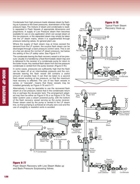
Condensate from high pressure loads releases steam by flashing<br />
as it passes to the lower pressures, downstream of the high<br />
pressure traps. The mixture of steam and condensate is readily<br />
separated in Flash Vessels of appropriate dimensions and<br />
proportions. A s<strong>up</strong>ply of Low Pressure steam then becomes<br />
available for use on any application which can accept steam at<br />
this low pressure, or the separated steam may simply be taken<br />
into the LP steam mains, where it is s<strong>up</strong>plemented through<br />
pressure reducing valves, for general plant use.<br />
Where the s<strong>up</strong>ply of flash steam may at times exceed the<br />
demand from the LP system, the surplus flash steam can be<br />
discharged through a back pressure control valve. This is set<br />
at a few psi above the normal LP steam pressure, but below<br />
the setting of the LP safety valve. See Figure II-77.<br />
The condensate leaving the flash recovery vessel is at low pressure.<br />
Usually it is handled by a float-thermostatic steam trap and<br />
is delivered to the receiver of a condensate pump for return to<br />
the boiler house. Any residual flash steam from the low pressure<br />
condensate is vented from the pump receiver. (Figure II-78.)<br />
In some cases, pressures are sufficiently high that the flash<br />
can be taken off at an intermediate pressure and the condensate<br />
leaving the flash vessel still contains a useful<br />
amount of sensible heat. It can then be taken to a second<br />
flash vessel working at low pressure, so that the maximum<br />
heat recovery is effected. The use of two flash vessels in<br />
series, or “cascade”, means that these vessels may be<br />
installed generally as Figure II-76 and II-77.<br />
Alternatively, it may be desirable to use the recovered flash<br />
steam at a low pressure, below that in the condensate return<br />
line or perhaps the de-aerator tank. The arrangement adapted<br />
may then be either as Figure II-78 or as Figure II-79. This<br />
latter system uses a steam powered pump, with the bottom<br />
of the flash recovery vessel serving as the pump receiver.<br />
Power steam used by the pump is vented to the LP steam<br />
line, so that pumping is achieved at virtually zero cost and the<br />
use of unsightly or wasteful vents is avoided.<br />
H. P.<br />
Steam<br />
S<strong>up</strong>ply<br />
Float &<br />
Thermostatic<br />
Steam Trap<br />
H. P. Condensate<br />
Strainer<br />
Spira-tec<br />
Loss<br />
Detector<br />
Moisture<br />
Separator<br />
Strainer<br />
H. P. Condensate<br />
Figure II-77<br />
Flash Steam Recovery with Live Steam Make <strong>up</strong><br />
and Back Pressure Surplussing Valves<br />
Drip<br />
Pan Elbow<br />
Drain to<br />
Safe<br />
Place<br />
Pilot Operated<br />
Pressure<br />
Control Valve<br />
Drain to<br />
Safe Place<br />
Safety<br />
Valve<br />
Flash<br />
Recovery<br />
Vessel<br />
Thermostatic<br />
Air Vent<br />
Safety<br />
Valve<br />
Flash<br />
Recovery<br />
Vessel<br />
Thermostatic<br />
Air Vent<br />
L. P. Steam Main<br />
Figure II-76<br />
Typical Flash Steam<br />
Recovery <strong>Hook</strong>-<strong>up</strong><br />
Spira-tec<br />
Loss<br />
Detector<br />
L. P.<br />
Strainer Float & Condensate<br />
Thermostatic<br />
Steam Trap<br />
Drip<br />
Pan<br />
Elbow<br />
Strainer<br />
Strainer<br />
L. P.<br />
Steam<br />
Spira-tec<br />
Loss Detector<br />
H. P. Condensate<br />
Float &<br />
Thermostatic<br />
Steam Trap<br />
Check<br />
Valve<br />
Vent<br />
Pilot Operated<br />
Back Pressure<br />
Control Valve<br />
L. P.<br />
Condensate