

2000 Hook-up Book - Spirax Sarco
2000 Hook-up Book - Spirax Sarco
2000 Hook-up Book - Spirax Sarco

Create successful ePaper yourself
Turn your PDF publications into a flip-book with our unique Google optimized e-Paper software.
Pressure Reducing Stations<br />
It is a mistake to install even the<br />
best of pressure reducing valves<br />
in a pipeline without giving some<br />
thought to how best it can be<br />
helped to give optimal performance.<br />
The valve selected should be<br />
of such a size that it can handle<br />
the necessary load, but oversizing<br />
should be avoided. The weight<br />
of steam to be handled in a given<br />
time must be calculated or estimated,<br />
and a valve capable of<br />
passing this weight from the<br />
given <strong>up</strong>stream pressure to the<br />
required downstream pressure is<br />
chosen. The valve size is usually<br />
smaller than the steam pipes<br />
either <strong>up</strong>stream or downstream,<br />
because of the high velocities<br />
which accompany the pressure<br />
drop within the valve.<br />
Types of Pressure Reducing<br />
Valves are also important and<br />
can be divided into three gro<strong>up</strong>s<br />
of operation as follows:<br />
Direct Operated Valves<br />
The direct acting valve shown in<br />
Fig. II-17 (page 91) is the simplest<br />
design of reducing valve.<br />
This type of valve has two<br />
drawbacks in that it allows greater<br />
fluctuation of the downstream<br />
pressure under unstable load<br />
demands, and these valves have<br />
relatively low capacity for their<br />
size. It is nevertheless perfectly<br />
adequate for a whole range of<br />
simple applications where accurate<br />
control is not essential and<br />
where the steam flow is fairly<br />
small and constant.<br />
Pilot Operated Valves<br />
Where accurate control of pressure<br />
or large capacity is required,<br />
a pilot operated reducing valve<br />
should be used. Such a valve is<br />
shown in Fig. II-12 (page 89).<br />
The pilot operated design<br />
offers a number of advantages over<br />
the direct acting valve. Only a very<br />
small amount of steam has to flow<br />
through the pilot valve to pressurize<br />
the main diaphragm chamber and<br />
fully open the main valve. Thus,<br />
only very small changes in downstream<br />
pressure are necessary to<br />
produce large changes in flow. The<br />
“droop” of pilot operated valves is<br />
therefore small. Although any rise<br />
in <strong>up</strong>stream pressure will apply an<br />
increased closing force on the main<br />
valve, this is offset by the force of<br />
the <strong>up</strong>stream pressure acting on<br />
the main diaphragm. The result is a<br />
valve which gives close control of<br />
downstream pressure regardless<br />
of variations on the <strong>up</strong>stream side.<br />
Pneumatically Operated<br />
Valves<br />
Pneumatically operated control<br />
valves, Fig. II-20 (page 93), with<br />
actuators and positioners being<br />
piloted by controllers, will provide<br />
pressure reduction with even<br />
more accurate control.<br />
Controllers sense downstream<br />
pressure fluctuations,<br />
interpolate the signals and regulate<br />
an air s<strong>up</strong>ply signal to a<br />
pneumatic positioner which in turn<br />
s<strong>up</strong>plies air to a disphragm opening<br />
a valve. Springs are utilized as<br />
an opposing force causing the<br />
valves to close <strong>up</strong>on a loss or<br />
reduction of air pressure applied<br />
on the diaphragm. Industry<br />
sophistication and control needs<br />
are demanding closer and more<br />
accurate control of steam pressures,<br />
making pneumatic control<br />
valves much more popular today.<br />
Piping And Noise Consideration<br />
The piping around a steam pressure<br />
reducing valve must be<br />
properly sized and fitted for best<br />
operation. Noise level of a reducing<br />
station is lowest when the<br />
valve is installed as follows:<br />
1. Avoid abr<strong>up</strong>t changes in<br />
direction of flow. Use long<br />
radius bends and “Y” piping<br />
instead of “T” connections.<br />
2. Limit approach and exit<br />
steam velocity to 4000 to<br />
6000 FPM.<br />
3. Change piping gradually<br />
Pressure Reducing Stations<br />
before and after the valve with<br />
tapered expanders, or change<br />
pipe only 1 or 2 sizes at a time.<br />
4. Provide long, straight, full-size<br />
runs of heavy wall pipe on<br />
both sides of the valve, and<br />
between two-stage reductions<br />
to stabilize the flow.<br />
5. Use low pressure turndown<br />
ratios (non-critical.)<br />
6. Install vibration absorbing<br />
pipe hangers and acoustical<br />
insulation.<br />
Most noise is generated by a<br />
reducing valve that operates at<br />
critical pressure drop, especially<br />
with high flow requirements.<br />
Fitting a noise diffuser directly to<br />
the valve outlet will reduce the<br />
noise level by approx. 15 dBA.<br />
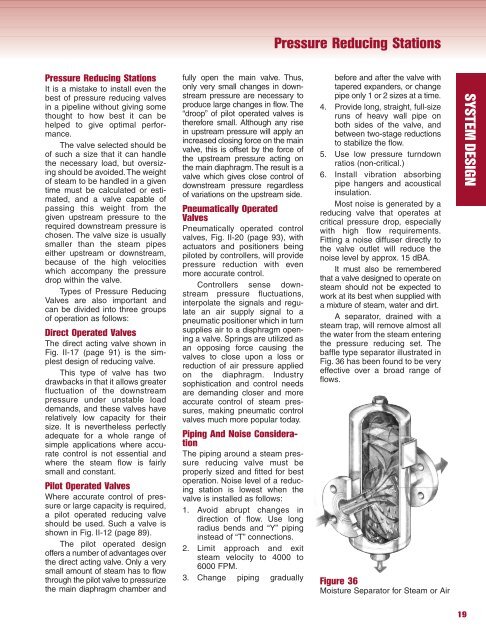
It must also be remembered<br />
that a valve designed to operate on<br />
steam should not be expected to<br />
work at its best when s<strong>up</strong>plied with<br />
a mixture of steam, water and dirt.<br />
A separator, drained with a<br />
steam trap, will remove almost all<br />
the water from the steam entering<br />
the pressure reducing set. The<br />
baffle type separator illustrated in<br />
Fig. 36 has been found to be very<br />
effective over a broad range of<br />
flows.<br />
Figure 36<br />
Moisture Separator for Steam or Air<br />
19<br />
SYSTEM DESIGN


