

2000 Hook-up Book - Spirax Sarco
2000 Hook-up Book - Spirax Sarco
2000 Hook-up Book - Spirax Sarco

Create successful ePaper yourself
Turn your PDF publications into a flip-book with our unique Google optimized e-Paper software.
Draining Steam Mains<br />
Note from the example that in<br />
most cases, other than large distribution<br />
mains, 1/2" Thermo-<br />
Dynamic ® traps have ample<br />
capacity. For shorter lengths<br />
between drip points, and for small<br />
diameter pipes, the 1/2" low<br />
capacity TD trap more than meets<br />
even start <strong>up</strong> loads, but on larger<br />
mains it may be worth fitting parallel<br />
1/2" traps as in Fig. II-6 (page<br />
86). Low pressure mains are best<br />
drained using float and thermostatic<br />
traps, and these traps can<br />
also be used at higher pressures.<br />
The design of drip stations<br />
are fairly simple. The most common<br />
rules to follow for sizing the<br />
drip pockets are:<br />
1. The diameter of the drip pockets<br />
shall be the same size as<br />
the distribution line <strong>up</strong> to 6<br />
inches in diameter.The diameter<br />
shall be half the size of the<br />
distribution line over 6 inches<br />
but never less than 6 inches.<br />
Steam Trap<br />
2. The length of the drip pocket<br />
shall be 1-1/2 times the diameter<br />
of the distribution line but<br />
not less than 18 inches.<br />
Drip Leg Spacing<br />
The spacing between the<br />
drainage points is often greater<br />
than is desirable. On a long horizontal<br />
run (or rather one with a<br />
fall in the direction of the flow of<br />
about 1/2" in 10 feet or 1/250)<br />
drain points should be provided at<br />
intervals of 100 to 200 feet.<br />
Longer lengths should be split <strong>up</strong><br />
by additional drain points. Any<br />
natural collecting points in the<br />
systems, such as at the foot of<br />
any riser, should also be drained.<br />
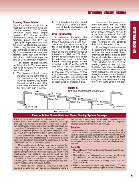
A very long run laid with a fall<br />
in this way may become so low<br />
that at intervals it must be elevated<br />
with a riser. The foot of each of<br />
these “relay points” also requires a<br />
collecting pocket and steam trap.<br />
Fall 1/2" in 10 Ft Steam<br />
Steam Trap<br />
Condensate<br />
Figure 5<br />
Draining and Relaying Steam Main<br />
Steam Trap<br />
Draining Steam Mains<br />
Sometimes the ground contours<br />
are such that the steam<br />
main can only be run <strong>up</strong>hill. This<br />
will mean the drain points should<br />
be at closer intervals, say 50 ft.<br />
apart, and the size of the main<br />
increased. The lower steam<br />
velocity then allows the condensate<br />
to drain in the opposite<br />
direction to the steam flow.<br />
Air venting of steam mains is<br />
of paramount importance and is<br />
far too often overlooked. Steam<br />
entering the pipes tends to push<br />
the air already there in front of it<br />
as would a piston. Automatic air<br />
vents, fitted on top of tees at the<br />
terminal points of the main and<br />
the larger branches, will allow discharge<br />
of this air. Absence of air<br />
vents means that the air will pass<br />
through the steam traps (where it<br />
may well slow down the discharge<br />
of condensate) or through<br />
the steam using equipment itself.<br />
Steam Trap<br />
Case in Action: Steam Main and Steam Tracing System Drainage<br />
The majority of steam traps in refineries are installed on<br />
steam main and steam tracing systems. Thorough<br />
drainage of steam mains/branch lines is essential for effective<br />
heat transfer around the refinery and for waterhammer<br />
prevention. This holds true for condensate drainage from<br />
steam tracing lines/jackets, though some degree of back<strong>up</strong><br />
(or sub-cooling) is permissible in some applications.<br />
The predominant steam trap installed is a nonrepairable<br />
type that incorporates a permanent pipeline<br />
connector. Scattered throughout the system are a number<br />
of iron and steel body repairable types.<br />
Most notable failure of steam traps are precipitate formation<br />
on bucket weep-holes and discharge orifices that<br />
eventually plugs the trap shut. A common culprit is valve<br />
sealing compound injected into leaking valves which forms<br />
small pellets that settle in low points, such as drip<br />
legs/steam traps and on strainer screens making blow<br />
down difficult. This problem also occurs during occasional<br />
“system <strong>up</strong>set” when hydrocarbon contaminants are mistakenly<br />
introduced to the steam system.<br />
A noise detector and/or a temperature-indicating<br />
device is required to detect trap failure. Especially costly is<br />
Steam Trap<br />
the fact that operators are not allowed to remove traps for<br />
repair when threading from the line is required.<br />
Maintenance personnel must be involved.<br />
Solution<br />
Universal connector steam traps were installed for trial in<br />
one of the dirtiest drip stations at the refinery. The traps<br />
held <strong>up</strong> under adverse operating conditions requiring only<br />
periodic cleaning. Since the time of installation, all failed<br />
inverted bucket traps in this service were replaced with universal<br />
connector traps. Strainers were installed <strong>up</strong>stream<br />
of each.<br />
Benefits<br />
• The addition of Thermo-Dynamic ® traps allowed for easier<br />
field trap testing.<br />
• The addition of universal connectors significantly<br />
reduced steam trap installation and repair time.<br />
• 33% reduction in steam trap inventory due to standard<br />
trap for all sizes.<br />
• Reduced energy loss is significantly reduced using Thermo-<br />
Dynamic ® steam traps versus original inverted bucket traps.<br />
11<br />
SYSTEM DESIGN


