

2000 Hook-up Book - Spirax Sarco
2000 Hook-up Book - Spirax Sarco
2000 Hook-up Book - Spirax Sarco

You also want an ePaper? Increase the reach of your titles
YUMPU automatically turns print PDFs into web optimized ePapers that Google loves.
The importance of effective condensate<br />
removal from steam<br />
spaces has been stressed<br />
throughout this course. If maximum<br />
steam system efficiency is<br />
to be achieved, the best type of<br />
steam trap must be fitted in the<br />
most suitable position for the<br />
application in question, the flash<br />
steam should be utilized, and the<br />
maximum amount of condensate<br />
should be recovered.<br />
There are a number of reasons<br />
why condensate should not<br />
be allowed to discharge to drain.<br />
The most important consideration<br />
is the valuable heat which it contains<br />
even after flash steam has<br />
been recovered. It is possible to<br />
use condensate as hot process<br />
water but the best arrangement is<br />
to return it to the boiler house,<br />
where it can be re-used as boiler<br />
feed water without further treatment,<br />
saving preheating fuel, raw<br />
water and the chemicals needed<br />
for boiler feed treatment. These<br />
savings will be even greater in<br />
cases where effluent charges<br />
have to be paid for the discharge<br />
of valuable hot condensate down<br />
the drain.<br />
Condensate recovery savings<br />
can add <strong>up</strong> to 20 to 25% of<br />
the plant’s steam generating<br />
costs. One justifiable reason for<br />
not returning condensate is the<br />
risk of contamination. Perforated<br />
coils in process vessels and heat<br />
exchangers do exist and the<br />
cross contamination of condensate<br />
and process fluids is always<br />
a danger. If there is any possibility<br />
that the condensate is<br />
contaminated, it must not be<br />
returned to the boiler. These<br />
problems have been lessened by<br />
the application of sensing systems<br />
monitoring the quality of<br />
condensate in different holding<br />
areas of a plant to determine condensate<br />
quality and providing a<br />
means to re-route the condensate<br />
if contaminated.<br />
Condensate Line Sizing<br />
Condensate recovery systems<br />
divide naturally into three sections,<br />
each section requiring<br />
different design considerations.<br />
a. Drain Lines to the traps carry<br />
pressurized high temperature<br />
hot water that moves by gravity.<br />
b. Trap discharge lines that<br />
carry a two-phase mixture of<br />
flash steam and condensate.<br />
c. Pumped return systems utilizing<br />
electric or non-electric<br />
pumps.<br />
Drain Lines To Traps<br />
In the first section, the condensate<br />
has to flow from the<br />
condensing surface to the steam<br />
trap. In most cases this means<br />
that gravity is relied on to induce<br />
flow, since the heat exchanger<br />
steam space and the traps are at<br />
the same pressure. The lines<br />
between the drainage points and<br />
the traps can be laid with a slight<br />
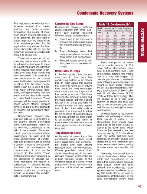
fall, say 1” in 10 feet, and Table 13<br />
shows the water carrying capacities<br />
of the pipes with such a<br />
gradient. It is important to allow<br />
for the passage of incondensibles<br />
to the trap, and for the extra water<br />
to be carried at cold starts. In<br />
most cases, it is sufficient to size<br />
these pipes on twice the full running<br />
load.<br />
Trap Discharge Lines<br />
At the outlet of steam traps, the<br />
condensate return lines must<br />
carry condensate, non-condensible<br />
gases and flash steam<br />
released from the condensate.<br />
Where possible, these lines<br />
should drain by gravity to the condensate<br />
receiver, whether this be<br />
a flash recovery vessel or the<br />
vented receiver of a pump. When<br />
sizing return lines, two important<br />
practical points must be considered.<br />
Condensate Recovery Systems<br />
Table 13: Condensate, lb/h<br />
Steel Approximate Frictional Resistance<br />
Pipe in inches Wg per 100 ft of Travel<br />
Size 1 5 7 10<br />
1/2" 100 240 290 350<br />
3/4" 230 560 680 820<br />
1" 440 1070 1200 1550<br />
1 1 /4" 950 2300 2700 3300<br />
1 1 /2" 1400 3500 4200 5000<br />
2" 2800 6800 8100 9900<br />
2 1 /2" 5700 13800 16500 <strong>2000</strong>0<br />
3" 9000 21500 25800 31000<br />
4" 18600 44000 5<strong>2000</strong> 63400<br />
First, one pound of steam<br />
has a specific volume of 26.8<br />
cubic feet at atmospheric pressure.<br />
It also contains 970 BTU’s<br />
of latent heat energy. This means<br />
that if a trap discharges 100<br />
pounds per hour of condensate<br />
from 100 psig to atmosphere, the<br />
weight of flash steam released<br />
will be 13.3 pounds per hour, having<br />
a total volume of 356.4 cubic<br />
feet. It will also have 12,901<br />
BTU’s of latent heat energy. This<br />
will appear to be a very large<br />
quantity of steam and may well<br />
lead to the erroneous conclusion<br />
that the trap is passing live steam<br />
(failed open).<br />
Another factor to be considered<br />
is that we have just released<br />
13.3 pounds of water to the<br />
atmosphere that should have<br />
gone back to the boiler house for<br />
recycling as boiler feed water.<br />
Since we just wasted it, we now<br />
have to s<strong>up</strong>ply 13.3 pounds of<br />
fresh city water that has been<br />
softened, chemically treated and<br />
preheated to the feedwater system’s<br />
temperature before putting<br />
this new water back into the boiler.<br />
Secondly, the actual formation<br />
of flash steam takes place<br />
within and downstream of the<br />
steam trap orifice where pressure<br />
drop occurs. From this point<br />
onward, the condensate return<br />
system must be capable of carrying<br />
this flash steam, as well as<br />
condensate. Unfortunately, in the<br />
past, condensate return lines<br />
45<br />
SYSTEM DESIGN


