

2000 Hook-up Book - Spirax Sarco
2000 Hook-up Book - Spirax Sarco
2000 Hook-up Book - Spirax Sarco

Create successful ePaper yourself
Turn your PDF publications into a flip-book with our unique Google optimized e-Paper software.
Make<strong>up</strong> air heating coils and<br />
other heat exchange equipment<br />
where the steam s<strong>up</strong>ply pressure<br />
is modulated to hold a desired<br />
outflow temperature must always<br />
be kept drained of condensate.<br />
Fitting a vacuum breaker and<br />
steam trap, no matter what the<br />
size, does not always result in<br />
trouble-free operation and problems<br />
with noisy, hammering,<br />
corroded and especially frozen<br />
coils are well documented. These<br />
problems are the result of coil<br />
flooding at some point when<br />
either:<br />
a. Incoming make<strong>up</strong> air increases<br />
above minimum design<br />
temperature, or<br />
b. Flow rate through an exchanger<br />
decreases below the<br />
maximum equipment output.<br />
In a steam system, temperature<br />
regulation actually means<br />
controlling the pressure. Under partial<br />
load conditions, the steam<br />
controller, whether self-acting,<br />
pneumatic or any other type,<br />
reduces the pressure until the necessary<br />
trap differential is eliminated,<br />
the system “stalls,” and steam coils<br />
become waterfilled coils.<br />
Conditions Creating “System<br />
Stall”<br />
With the steam equipment and<br />
the operating pressure selected,<br />
the load at which any system<br />
stalls is a function of how close<br />
the equipment is sized to the<br />
actual load and any condensate<br />
elevation or other back pressure<br />
the trap is subject to.<br />
Other less obvious things can<br />
also seriously contribute to “system<br />
stall”; for instance, overly<br />
generous fouling factors and<br />
equipment oversizing. As an<br />
example, a fouling factor of “only”<br />
.001 can result in a coil surface<br />
area increase of 50% (See Table<br />
10). Equipment oversizing causes<br />
the system to stall faster. This is<br />
particularly the case when the<br />
heating equipment is expected to<br />
run considerably below “design<br />
load.”<br />
Saturated steam temperature<br />
is directly related to its pressure<br />
Draining Temperature Controlled Steam Equipment<br />
and for any load requirement, the<br />
control valve output is determined<br />
by the basic heat transfer equation,<br />
Q = UA x ∆T. With “UA” for a<br />
steam-filled coil a constant, the<br />
amount of heat s<strong>up</strong>plied, “Q”, is<br />
regulated by the “∆T,” the log<br />
mean temperature difference<br />
(LMTD) between the heated air or<br />
liquid and saturated steam temperature<br />
at the pressure delivered<br />
by the valve. Thus, the steam<br />
pressure available to operate the<br />
trap is not constant but varies with<br />
the demand for heat from almost<br />
line pressure down through subatmospheric,<br />
to complete<br />
shutdown when no heat is<br />
required. Actual differential across<br />
the trap is further reduced when<br />
the heating surface is oversized or<br />
the trap must discharge against a<br />
back pressure. Knowing these<br />
conditions, the system must be<br />
designed accordingly.<br />
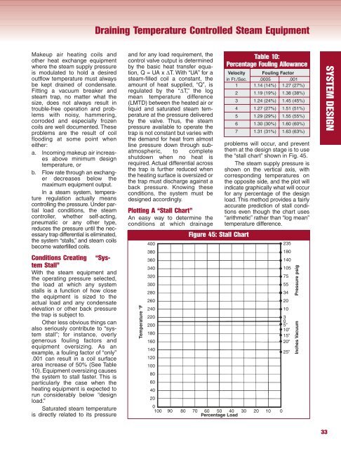
Plotting A “Stall Chart”<br />
An easy way to determine the<br />
conditions at which drainage<br />
Temperature °F<br />
400<br />
380<br />
360<br />
340<br />
320<br />
300<br />
280<br />
260<br />
240<br />
220<br />
200<br />
180<br />
160<br />
140<br />
120<br />
100<br />
80<br />
60<br />
40<br />
20<br />
Figure 45: Stall Chart<br />
Table 10:<br />
Percentage Fouling Allowance<br />
Velocity Fouling Factor<br />
in Ft./Sec. .0005 .001<br />
1 1.14 (14%) 1.27 (27%)<br />
2 1.19 (19%) 1.38 (38%)<br />
3 1.24 (24%) 1.45 (45%)<br />
4 1.27 (27%) 1.51 (51%)<br />
5 1.29 (29%) 1.55 (55%)<br />
6 1.30 (30%) 1.60 (60%)<br />
7 1.31 (31%) 1.63 (63%)<br />
problems will occur, and prevent<br />
them at the design stage is to use<br />
the “stall chart” shown in Fig. 45.<br />
The steam s<strong>up</strong>ply pressure is<br />
shown on the vertical axis, with<br />
corresponding temperatures on<br />
the opposite side, and the plot will<br />
indicate graphically what will occur<br />
for any percentage of the design<br />
load. This method provides a fairly<br />
accurate prediction of stall conditions<br />
even though the chart uses<br />
“arithmetic” rather than “log mean”<br />
temperature difference.<br />
0<br />
100 90 80 70 60 50 40<br />
Percentage Load<br />
30 20 10 0<br />
235<br />
180<br />
140<br />
105<br />
psig<br />
75<br />
55<br />
34 Pressure<br />
20<br />
10<br />
3<br />
0<br />
5"<br />
10"<br />
15" Vacuum<br />
20"<br />
25" Inches<br />
33<br />
SYSTEM DESIGN


