Urma Digiset 5 USERMANUAL - Urma AG
Urma Digiset 5 USERMANUAL - Urma AG
Urma Digiset 5 USERMANUAL - Urma AG

Create successful ePaper yourself
Turn your PDF publications into a flip-book with our unique Google optimized e-Paper software.
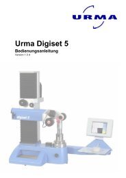
digiset 5<br />
6.2 Imaging<br />
6.2.1 Coordinate system (optional)<br />
The names of the vertical and horizontal axes often vary with measuring instruments.<br />
And so vertical and horizontal adjustment devices also differ in their axis assignment<br />
for example.<br />
This operating mode is therefore used for the axis assignment (X = horizontal or vertical,<br />
Z = vertical or horizontal) including the imaging axes with the counter module<br />
axes.<br />
You access this operating mode using the following menu steps:<br />
Main menu Sub-menu 1 Sub-menu 2<br />
Setup � Imaging � Coordinate system<br />
6.2.2 Black/White<br />
You access this operating mode using the following menu steps:<br />
Main menu Sub-menu 1 Sub-menu 2<br />
Setup � Imaging � Black/White<br />
Here you can decide whether an object and its contour are displayed in colour (false<br />
colours) or in black and white (grey scale).<br />
The standard setting with false colours is used for the transmitted light application.<br />
It gives optimum optical contrast for your observations and is the basis for precise<br />
measuring results.<br />
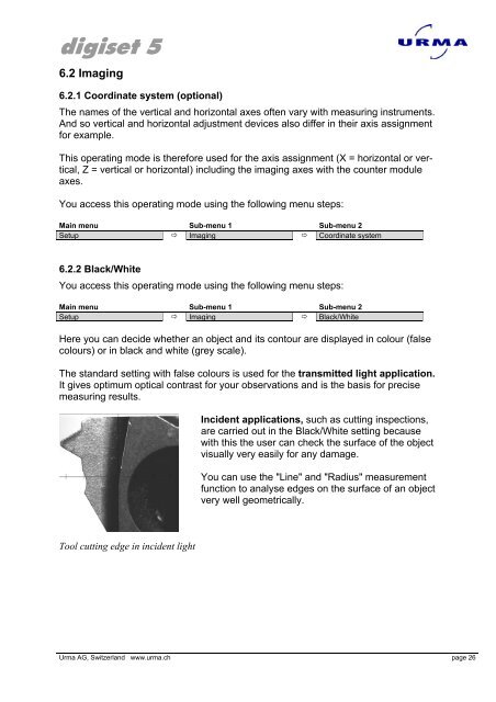
Tool cutting edge in incident light<br />
Incident applications, such as cutting inspections,<br />
are carried out in the Black/White setting because<br />
with this the user can check the surface of the object<br />
visually very easily for any damage.<br />
You can use the "Line" and "Radius" measurement<br />
function to analyse edges on the surface of an object<br />
very well geometrically.<br />
<strong>Urma</strong> <strong>AG</strong>, Switzerland www.urma.ch page 26