- Page 1 and 2:
SIPROTEC Differential Protection 7U
- Page 4 and 5:
Preface Additional Support Training
- Page 6 and 7:
Preface Typographic and Symbol Conv
- Page 8 and 9:
Preface 8 SIPROTEC, 7UT6x, Manual C
- Page 10 and 11:
Contents 10 2.2 Differential Protec
- Page 12 and 13:
Contents 12 2.14 Undervoltage Prote
- Page 14 and 15:
Contents 14 2.23 Average Values, Mi
- Page 16 and 17:
Contents A Appendix. . . . . . . .
- Page 18 and 19:
Introduction 1.1 Overall Operation
- Page 20 and 21:
Introduction 1.1 Overall Operation
- Page 22 and 23:
Introduction 1.2 Application Scope
- Page 24 and 25:
Introduction 1.3 Characteristics Di
- Page 26 and 27:
Introduction 1.3 Characteristics Un
- Page 28 and 29:
Introduction 1.3 Characteristics Ex
- Page 30 and 31:
Introduction 1.3 Characteristics 30
- Page 32 and 33:
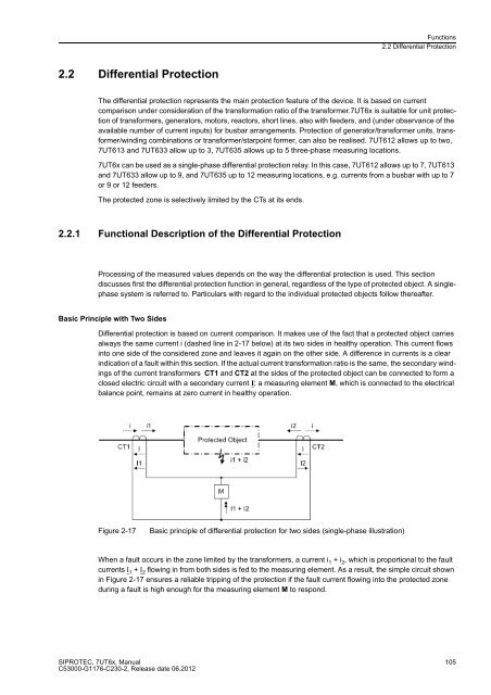
Functions 2.1 General 2.1 General 3
- Page 34 and 35:
Functions 2.1 General 2.1.1.3 Infor
- Page 36 and 37:
Functions 2.1 General 2.1.3 Configu
- Page 38 and 39:
Functions 2.1 General Differential
- Page 40 and 41:
Functions 2.1 General Single-phase
- Page 42 and 43:
Functions 2.1 General Undervoltage
- Page 44 and 45:
Functions 2.1 General 44 Addr. Para
- Page 46 and 47:
Functions 2.1 General 2.1.4 Power S
- Page 48 and 49:
Functions 2.1 General 48 Figure 2-2
- Page 50 and 51:
Functions 2.1 General 50 Note If yo
- Page 52 and 53:
Functions 2.1 General Special Consi
- Page 54: Functions 2.1 General 54 Current co
- Page 57 and 58: SIPROTEC, 7UT6x, Manual C53000-G117
- Page 59 and 60: SIPROTEC, 7UT6x, Manual C53000-G117
- Page 61 and 62: Assignment of Voltage Measuring Inp
- Page 63 and 64: Figure 2-9 Power measurement at gen
- Page 66 and 67: Functions 2.1 General 66 The mode o
- Page 68 and 69: Functions 2.1 General Figure 2-12 R
- Page 70 and 71: Functions 2.1 General Current Trans
- Page 72 and 73: Functions 2.1 General 72 Similar ap
- Page 74 and 75: Functions 2.1 General 74 Hereinafte
- Page 76: Functions 2.1 General 76 Figure 2-1
- Page 80 and 81: Functions 2.1 General 80 As the abo
- Page 82 and 83: Functions 2.1 General 2.1.4.4 Circu
- Page 84 and 85: Functions 2.1 General 84 Addr. Para
- Page 86 and 87: Functions 2.1 General 86 Addr. Para
- Page 88 and 89: Functions 2.1 General 88 Addr. Para
- Page 90 and 91: Functions 2.1 General 90 Addr. Para
- Page 92 and 93: Functions 2.1 General 92 Addr. Para
- Page 94 and 95: Functions 2.1 General 94 Addr. Para
- Page 96 and 97: Functions 2.1 General 2.1.5 Setting
- Page 99 and 100: SIPROTEC, 7UT6x, Manual C53000-G117
- Page 101 and 102: Addr. Parameter C Setting Options D
- Page 103: No. Information Type of Information
- Page 107: SIPROTEC, 7UT6x, Manual C53000-G117
- Page 113 and 114: Figure 2-25 Tripping logic of the d
- Page 115 and 116: SIPROTEC, 7UT6x, Manual C53000-G117
- Page 117 and 118: Earthed Starpoint SIPROTEC, 7UT6x,
- Page 119 and 120: SIPROTEC, 7UT6x, Manual C53000-G117
- Page 121 and 122: Use on Single-phase Auto-transforme
- Page 123 and 124: 2.2.3 Differential Protection for G
- Page 125 and 126: 2.2.5 Differential Protection for M
- Page 127 and 128: 2.2.6 Single-phase Differential Pro
- Page 131 and 132: SIPROTEC, 7UT6x, Manual C53000-G117
- Page 134: Functions 2.2 Differential Protecti
- Page 140 and 141: Functions 2.3 Restricted Earth Faul
- Page 142 and 143: Functions 2.3 Restricted Earth Faul
- Page 144 and 145: Functions 2.3 Restricted Earth Faul
- Page 146: Functions 2.3 Restricted Earth Faul
- Page 150: Functions 2.3 Restricted Earth Faul
- Page 153 and 154: SIPROTEC, 7UT6x, Manual C53000-G117
- Page 155 and 156:
SIPROTEC, 7UT6x, Manual C53000-G117
- Page 157 and 158:
2.4.1.2 Inverse Time Overcurrent Pr
- Page 159 and 160:
SIPROTEC, 7UT6x, Manual C53000-G117
- Page 161 and 162:
2.4.1.5 Inrush Restraint SIPROTEC,
- Page 163 and 164:
Figure 2-74 Fast busbar protection
- Page 168:
Functions 2.4 Time Overcurrent Prot
- Page 173 and 174:
2.4.2.3 Information List No. Inform
- Page 178:
Functions 2.4 Time Overcurrent Prot
- Page 182 and 183:
Functions 2.5 Time Overcurrent Prot
- Page 184 and 185:
Functions 2.5 Time Overcurrent Prot
- Page 186 and 187:
Functions 2.5 Time Overcurrent Prot
- Page 188:
Functions 2.5 Time Overcurrent Prot
- Page 196 and 197:
Functions 2.6 Dynamic Cold Load Pic
- Page 198:
Functions 2.6 Dynamic Cold Load Pic
- Page 202 and 203:
Functions 2.7 Single-Phase Time Ove
- Page 204:
Functions 2.7 Single-Phase Time Ove
- Page 211 and 212:
2.8 Unbalanced Load Protection SIPR
- Page 213 and 214:
Pickup, Trip Dropout SIPROTEC, 7UT6
- Page 215 and 216:
Thermal Stage Pickup, Warning Therm
- Page 217 and 218:
Logic SIPROTEC, 7UT6x, Manual C5300
- Page 219:
SIPROTEC, 7UT6x, Manual C53000-G117
- Page 223:
Example: Machine I N = 483 A SIPROT
- Page 230:
Functions 2.9 Thermal Overload Prot
- Page 236:
Functions 2.9 Thermal Overload Prot
- Page 246 and 247:
Functions 2.11 Overexcitation Prote
- Page 249 and 250:
SIPROTEC, 7UT6x, Manual C53000-G117
- Page 253:
Delay and Logic Two delay times are
- Page 258 and 259:
Functions 2.13 Forward Power Superv
- Page 262:
Functions 2.14 Undervoltage Protect
- Page 267:
2.15.1 Function Description SIPROTE
- Page 271:
Figure 2-106 Logic diagram of frequ
- Page 275 and 276:
2.16.4 Information List No. Informa
- Page 277 and 278:
SIPROTEC, 7UT6x, Manual C53000-G117
- Page 279 and 280:
Delay Time and Breaker Failure Trip
- Page 281 and 282:
Initiation SIPROTEC, 7UT6x, Manual
- Page 285 and 286:
2.18 External Trip Commands 2.18.1
- Page 288 and 289:
Functions 2.19 Monitoring Functions
- Page 290:
Functions 2.19 Monitoring Functions
- Page 294:
Functions 2.19 Monitoring Functions
- Page 297 and 298:
SIPROTEC, 7UT6x, Manual C53000-G117
- Page 299 and 300:
SIPROTEC, 7UT6x, Manual C53000-G117
- Page 301 and 302:
The following figure shows the logi
- Page 303:
SIPROTEC, 7UT6x, Manual C53000-G117
- Page 307:
No. Information Type of Information
- Page 310 and 311:
Functions 2.20 Protection Function
- Page 312 and 313:
Functions 2.20 Protection Function
- Page 314 and 315:
Functions 2.21 Disconnection of Mea
- Page 316 and 317:
Functions 2.22 Additional Functions
- Page 318 and 319:
Functions 2.22 Additional Functions
- Page 322:
Functions 2.22 Additional Functions
- Page 329 and 330:
2.22.4 Differential and Restraining
- Page 332 and 333:
Functions 2.22 Additional Functions
- Page 334 and 335:
Functions 2.22 Additional Functions
- Page 336 and 337:
Functions 2.22 Additional Functions
- Page 338 and 339:
Functions 2.22 Additional Functions
- Page 340 and 341:
Functions 2.22 Additional Functions
- Page 342 and 343:
Functions 2.22 Additional Functions
- Page 345 and 346:
2.22.10 Commissioning Aids SIPROTEC
- Page 347 and 348:
2.23 Average Values, Minimum and Ma
- Page 349 and 350:
2.23.2 Min/Max Measurement Setup 2.
- Page 352 and 353:
Functions 2.24 Command Processing C
- Page 354 and 355:
Functions 2.24 Command Processing 3
- Page 356 and 357:
Functions 2.24 Command Processing 3
- Page 358 and 359:
Functions 2.24 Command Processing 3
- Page 360 and 361:
Mounting and Commissioning 3.1 Moun
- Page 362 and 363:
Mounting and Commissioning 3.1 Moun
- Page 365 and 366:
RTD-Box SIPROTEC, 7UT6x, Manual C53
- Page 367 and 368:
The ratings of the fuse are printed
- Page 369 and 370:
Board Arrangement 7UT613/63x SIPROT
- Page 371 and 372:
3.1.2.3 Switching Elements on Print
- Page 373 and 374:
Processor Module C-CPU-2 SIPROTEC,
- Page 375 and 376:
SIPROTEC, 7UT6x, Manual C53000-G117
- Page 377 and 378:
SIPROTEC, 7UT6x, Manual C53000-G117
- Page 379 and 380:
SIPROTEC, 7UT6x, Manual C53000-G117
- Page 381 and 382:
Input/Output Board C-I/O-2 (only 7U
- Page 383 and 384:
The input/output board C-I/O-2 carr
- Page 385 and 386:
SIPROTEC, 7UT6x, Manual C53000-G117
- Page 387 and 388:
Input/Output Board C-I/O-9 (only 7U
- Page 389 and 390:
Table 3-22 Assignment of jumpers fo
- Page 391 and 392:
Note SIPROTEC, 7UT6x, Manual C53000
- Page 393 and 394:
Table 3-24 Exchange Interface Modul
- Page 395 and 396:
RS485 Interface SIPROTEC, 7UT6x, Ma
- Page 397 and 398:
3.1.3 Mounting 3.1.3.1 Panel Flush
- Page 399 and 400:
3.1.3.2 Rack and Cubicle Mounting S
- Page 401 and 402:
Figure 3-25 Installation of a 7UT63
- Page 403 and 404:
SIPROTEC, 7UT6x, Manual C53000-G117
- Page 405 and 406:
System interface SIPROTEC, 7UT6x, M
- Page 407 and 408:
RTD box SIPROTEC, 7UT6x, Manual C53
- Page 409 and 410:
SIPROTEC, 7UT6x, Manual C53000-G117
- Page 411 and 412:
3.3.1 Test Mode / Transmission Bloc
- Page 413 and 414:
Structure of the Dialog Box SIPROTE
- Page 415 and 416:
Structure of the Dialog Box SIPROTE
- Page 417 and 418:
An update is made: Exiting the Proc
- Page 419 and 420:
SIPROTEC, 7UT6x, Manual C53000-G117
- Page 421 and 422:
Table 3-30 Indications on matching
- Page 425 and 426:
Flexible Functions Current Function
- Page 428 and 429:
Mounting and Commissioning 3.3 Comm
- Page 430 and 431:
Mounting and Commissioning 3.3 Comm
- Page 435:
SIPROTEC, 7UT6x, Manual C53000-G117
- Page 438 and 439:
Mounting and Commissioning 3.3 Comm
- Page 440:
Mounting and Commissioning 3.3 Comm
- Page 444 and 445:
Mounting and Commissioning 3.3 Comm
- Page 447 and 448:
Figure 3-46 Phasor Diagram of the P
- Page 451 and 452:
SIPROTEC, 7UT6x, Manual C53000-G117
- Page 454 and 455:
Mounting and Commissioning 3.4 Fina
- Page 456:
Technical Data 4.1 General 4.1 Gene
- Page 460:
Technical Data 4.1 General 4.1.5 Co
- Page 473 and 474:
Operating Range Frequency (Transfor
- Page 475 and 476:
Operating Times (Generators, Motors
- Page 477:
Operating Time (Busbars, Short Line
- Page 484 and 485:
Technical Data 4.4 Time Overcurrent
- Page 488 and 489:
Technical Data 4.4 Time Overcurrent
- Page 490 and 491:
Technical Data 4.4 Time Overcurrent
- Page 500:
Technical Data 4.8 Unbalanced Load
- Page 504:
Technical Data 4.8 Unbalanced Load
- Page 510:
Technical Data 4.11 Overexcitation
- Page 520 and 521:
Technical Data 4.20 User-defined Fu
- Page 522 and 523:
Technical Data 4.20 User-defined Fu
- Page 529 and 530:
Time Synchronisation Commissioning
- Page 531 and 532:
4.23.3 Panel Surface Mounting (Encl
- Page 533 and 534:
4.23.5 Panel Surface and Cabinet Mo
- Page 535 and 536:
4.23.7 RTD box Figure 4-26 Dimensio
- Page 537 and 538:
Appendix A This appendix is primari
- Page 539 and 540:
Additional Specification L for Furt
- Page 541 and 542:
Additional Specification L for Furt
- Page 543 and 544:
SIPROTEC, 7UT6x, Manual C53000-G117
- Page 545 and 546:
1) Only in connection with position
- Page 547 and 548:
Exchangeable Interface Modules SIPR
- Page 549 and 550:
SIMATIC CFC 4 Varistor SIPROTEC, 7U
- Page 551 and 552:
7UT613*-*D/E Figure A-2 Overview di
- Page 553 and 554:
7UT633*-* D/E Figure A-3 General di
- Page 555 and 556:
7UT633*-* P/Q Figure A-4 General di
- Page 557 and 558:
7UT635*-* D/E Figure A-5 General di
- Page 559 and 560:
7UT635*-* P/Q Figure A-6 General di
- Page 561 and 562:
7UT613*-* B Figure A-8 General diag
- Page 563 and 564:
7UT633*-* B Figure A-9 General diag
- Page 565 and 566:
7UT633*-* N Figure A-10 General dia
- Page 567 and 568:
7UT635*-* B Figure A-11 General dia
- Page 569 and 570:
7UT635*-* N Figure A-12 General dia
- Page 571 and 572:
SIPROTEC, 7UT6x, Manual C53000-G117
- Page 573 and 574:
SIPROTEC, 7UT6x, Manual C53000-G117
- Page 575 and 576:
SIPROTEC, 7UT6x, Manual C53000-G117
- Page 577 and 578:
Figure A-22 Connection example 7UT6
- Page 579 and 580:
SIPROTEC, 7UT6x, Manual C53000-G117
- Page 581 and 582:
SIPROTEC, 7UT6x, Manual C53000-G117
- Page 583 and 584:
A.3.2 Voltage Transformer Connectio
- Page 585:
A.3.3 Assignment of Protection Func
- Page 590 and 591:
Appendix A.5 Default Settings A.5 D
- Page 592 and 593:
Appendix A.5 Default Settings A.5.5
- Page 594:
Appendix A.5 Default Settings A.5.6
- Page 597 and 598:
Addr. Parameter Setting Options Def
- Page 599 and 600:
A.8 Settings Addresses which have a
- Page 601 and 602:
Addr. Parameter Function C Setting
- Page 603 and 604:
Addr. Parameter Function C Setting
- Page 605 and 606:
Addr. Parameter Function C Setting
- Page 607 and 608:
Addr. Parameter Function C Setting
- Page 609:
Addr. Parameter Function C Setting
- Page 629 and 630:
A.9 Information List SIPROTEC, 7UT6
- Page 631 and 632:
No. Description Function Type of In
- Page 633:
No. Description Function Type of In
- Page 637:
No. Description Function Type of In
- Page 640 and 641:
Appendix A.9 Information List 640 N
- Page 642 and 643:
Appendix A.9 Information List 642 N
- Page 644 and 645:
Appendix A.9 Information List 644 N
- Page 646:
Appendix A.9 Information List 646 N
- Page 650 and 651:
Appendix A.9 Information List 650 N
- Page 652 and 653:
Appendix A.9 Information List 652 N
- Page 654 and 655:
Appendix A.9 Information List 654 N
- Page 656 and 657:
Appendix A.9 Information List 656 N
- Page 658:
Appendix A.9 Information List 658 N
- Page 663:
SIPROTEC, 7UT6x, Manual C53000-G117
- Page 669 and 670:
Literature /1/ SIPROTEC 4 System Ma
- Page 677:
LVU Master Metered value MLFB Modem
- Page 683 and 684:
Index A Acknowledgement of commands
- Page 685 and 686:
Fault Value Storage Storage Criteri
- Page 687 and 688:
P Parameter Group Changeover 36, 97
- Page 689 and 690:
Z Zero Current 124 Zero Sequence Cu