- Page 1 and 2:
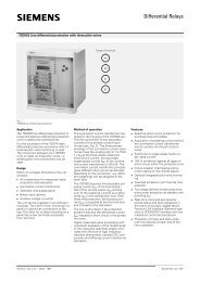
SIPROTEC Differential Protection 7U
- Page 4 and 5:
Preface Additional Support Training
- Page 6 and 7:
Preface Typographic and Symbol Conv
- Page 8 and 9:
Preface 8 SIPROTEC, 7UT6x, Manual C
- Page 10 and 11:
Contents 10 2.2 Differential Protec
- Page 12 and 13:
Contents 12 2.14 Undervoltage Prote
- Page 14 and 15:
Contents 14 2.23 Average Values, Mi
- Page 16 and 17:
Contents A Appendix. . . . . . . .
- Page 18 and 19:
Introduction 1.1 Overall Operation
- Page 20 and 21:
Introduction 1.1 Overall Operation
- Page 22 and 23:
Introduction 1.2 Application Scope
- Page 24 and 25:
Introduction 1.3 Characteristics Di
- Page 26 and 27:
Introduction 1.3 Characteristics Un
- Page 28 and 29:
Introduction 1.3 Characteristics Ex
- Page 30 and 31:
Introduction 1.3 Characteristics 30
- Page 32 and 33:
Functions 2.1 General 2.1 General 3
- Page 34 and 35:
Functions 2.1 General 2.1.1.3 Infor
- Page 36 and 37:
Functions 2.1 General 2.1.3 Configu
- Page 38 and 39:
Functions 2.1 General Differential
- Page 40 and 41:
Functions 2.1 General Single-phase
- Page 42 and 43:
Functions 2.1 General Undervoltage
- Page 44 and 45:
Functions 2.1 General 44 Addr. Para
- Page 46 and 47:
Functions 2.1 General 2.1.4 Power S
- Page 48 and 49:
Functions 2.1 General 48 Figure 2-2
- Page 50 and 51:
Functions 2.1 General 50 Note If yo
- Page 52 and 53:
Functions 2.1 General Special Consi
- Page 54:
Functions 2.1 General 54 Current co
- Page 57 and 58:
SIPROTEC, 7UT6x, Manual C53000-G117
- Page 59 and 60:
SIPROTEC, 7UT6x, Manual C53000-G117
- Page 61 and 62:
Assignment of Voltage Measuring Inp
- Page 63 and 64:
Figure 2-9 Power measurement at gen
- Page 66 and 67:
Functions 2.1 General 66 The mode o
- Page 68 and 69:
Functions 2.1 General Figure 2-12 R
- Page 70 and 71:
Functions 2.1 General Current Trans
- Page 72 and 73:
Functions 2.1 General 72 Similar ap
- Page 74 and 75:
Functions 2.1 General 74 Hereinafte
- Page 76:
Functions 2.1 General 76 Figure 2-1
- Page 80 and 81:
Functions 2.1 General 80 As the abo
- Page 82 and 83:
Functions 2.1 General 2.1.4.4 Circu
- Page 84 and 85:
Functions 2.1 General 84 Addr. Para
- Page 86 and 87:
Functions 2.1 General 86 Addr. Para
- Page 88 and 89:
Functions 2.1 General 88 Addr. Para
- Page 90 and 91:
Functions 2.1 General 90 Addr. Para
- Page 92 and 93:
Functions 2.1 General 92 Addr. Para
- Page 94 and 95:
Functions 2.1 General 94 Addr. Para
- Page 96 and 97:
Functions 2.1 General 2.1.5 Setting
- Page 99 and 100:
SIPROTEC, 7UT6x, Manual C53000-G117
- Page 101 and 102:
Addr. Parameter C Setting Options D
- Page 103 and 104:
No. Information Type of Information
- Page 105 and 106:
2.2 Differential Protection SIPROTE
- Page 107:
SIPROTEC, 7UT6x, Manual C53000-G117
- Page 113 and 114: Figure 2-25 Tripping logic of the d
- Page 115 and 116: SIPROTEC, 7UT6x, Manual C53000-G117
- Page 117 and 118: Earthed Starpoint SIPROTEC, 7UT6x,
- Page 119 and 120: SIPROTEC, 7UT6x, Manual C53000-G117
- Page 121 and 122: Use on Single-phase Auto-transforme
- Page 123 and 124: 2.2.3 Differential Protection for G
- Page 125 and 126: 2.2.5 Differential Protection for M
- Page 127 and 128: 2.2.6 Single-phase Differential Pro
- Page 131 and 132: SIPROTEC, 7UT6x, Manual C53000-G117
- Page 134: Functions 2.2 Differential Protecti
- Page 140 and 141: Functions 2.3 Restricted Earth Faul
- Page 142 and 143: Functions 2.3 Restricted Earth Faul
- Page 144 and 145: Functions 2.3 Restricted Earth Faul
- Page 146: Functions 2.3 Restricted Earth Faul
- Page 150: Functions 2.3 Restricted Earth Faul
- Page 153 and 154: SIPROTEC, 7UT6x, Manual C53000-G117
- Page 155 and 156: SIPROTEC, 7UT6x, Manual C53000-G117
- Page 157 and 158: 2.4.1.2 Inverse Time Overcurrent Pr
- Page 159 and 160: SIPROTEC, 7UT6x, Manual C53000-G117
- Page 161 and 162: 2.4.1.5 Inrush Restraint SIPROTEC,
- Page 163: Figure 2-74 Fast busbar protection
- Page 170: Functions 2.4 Time Overcurrent Prot
- Page 174: Functions 2.4 Time Overcurrent Prot
- Page 181 and 182: 2.4.3.3 Information List No. Inform
- Page 183 and 184: 2.5.2 Definite Time, Instantaneous
- Page 185 and 186: 2.5.3 Inverse Time Overcurrent Prot
- Page 187 and 188: User-defined Characteristics SIPROT
- Page 194: Functions 2.5 Time Overcurrent Prot
- Page 197 and 198: SIPROTEC, 7UT6x, Manual C53000-G117
- Page 201 and 202: SIPROTEC, 7UT6x, Manual C53000-G117
- Page 203 and 204: Figure 2-87 Earth fault protection
- Page 210 and 211: Functions 2.7 Single-Phase Time Ove
- Page 212 and 213: Functions 2.8 Unbalanced Load Prote
- Page 214 and 215:
Functions 2.8 Unbalanced Load Prote
- Page 216 and 217:
Functions 2.8 Unbalanced Load Prote
- Page 218 and 219:
Functions 2.8 Unbalanced Load Prote
- Page 222 and 223:
Functions 2.8 Unbalanced Load Prote
- Page 228:
Functions 2.9 Thermal Overload Prot
- Page 232:
Functions 2.9 Thermal Overload Prot
- Page 245 and 246:
2.10.4 Information List No. Informa
- Page 247:
Figure 2-99 Logic diagram of the ov
- Page 250:
Functions 2.11 Overexcitation Prote
- Page 255:
SIPROTEC, 7UT6x, Manual C53000-G117
- Page 259:
2.13.2 Setting Notes General Pickup
- Page 266 and 267:
Functions 2.15 Overvoltage Protecti
- Page 270 and 271:
Functions 2.16 Frequency Protection
- Page 273:
Setting example: SIPROTEC, 7UT6x, M
- Page 276 and 277:
Functions 2.17 Circuit Breaker Fail
- Page 278 and 279:
Functions 2.17 Circuit Breaker Fail
- Page 280 and 281:
Functions 2.17 Circuit Breaker Fail
- Page 282:
Functions 2.17 Circuit Breaker Fail
- Page 286:
Functions 2.18 External Trip Comman
- Page 289 and 290:
Sampling Frequency SIPROTEC, 7UT6x,
- Page 293 and 294:
2.19.1.4 Setting Notes Measured Val
- Page 296 and 297:
Functions 2.19 Monitoring Functions
- Page 298 and 299:
Functions 2.19 Monitoring Functions
- Page 300 and 301:
Functions 2.19 Monitoring Functions
- Page 302 and 303:
Functions 2.19 Monitoring Functions
- Page 306 and 307:
Functions 2.19 Monitoring Functions
- Page 309 and 310:
SIPROTEC, 7UT6x, Manual C53000-G117
- Page 311 and 312:
2.20.2 Tripping Logic for the Entir
- Page 313 and 314:
2.21 Disconnection of Measuring Loc
- Page 315 and 316:
2.21.2 Information List No. Informa
- Page 317 and 318:
Information on the Integrated Displ
- Page 319:
2.22.1.4 Spontaneous Annunciations
- Page 325:
No. Information Type of Information
- Page 330:
Functions 2.22 Additional Functions
- Page 333 and 334:
Processing Blocking Violation of th
- Page 335 and 336:
SIPROTEC, 7UT6x, Manual C53000-G117
- Page 337 and 338:
Additional Steps SIPROTEC, 7UT6x, M
- Page 339 and 340:
SIPROTEC, 7UT6x, Manual C53000-G117
- Page 341 and 342:
2.22.8 Flexible Function 2.22.8.1 S
- Page 343:
2.22.9 Oscillographic Fault Recordi
- Page 346 and 347:
Functions 2.22 Additional Functions
- Page 348 and 349:
Functions 2.23 Average Values, Mini
- Page 350:
Functions 2.24 Command Processing 2
- Page 353 and 354:
Type of Command Control Cause Indic
- Page 355 and 356:
Standard Interlocking SIPROTEC, 7UT
- Page 357 and 358:
Command output/switching relays SIP
- Page 359 and 360:
Mounting and Commissioning 3 This c
- Page 361 and 362:
Voltages SIPROTEC, 7UT6x, Manual C5
- Page 363:
Trip Circuit Supervision SIPROTEC,
- Page 366 and 367:
Mounting and Commissioning 3.1 Moun
- Page 368 and 369:
Mounting and Commissioning 3.1 Moun
- Page 370 and 371:
Mounting and Commissioning 3.1 Moun
- Page 372 and 373:
Mounting and Commissioning 3.1 Moun
- Page 374 and 375:
Mounting and Commissioning 3.1 Moun
- Page 376 and 377:
Mounting and Commissioning 3.1 Moun
- Page 378 and 379:
Mounting and Commissioning 3.1 Moun
- Page 380 and 381:
Mounting and Commissioning 3.1 Moun
- Page 382 and 383:
Mounting and Commissioning 3.1 Moun
- Page 384 and 385:
Mounting and Commissioning 3.1 Moun
- Page 386 and 387:
Mounting and Commissioning 3.1 Moun
- Page 388 and 389:
Mounting and Commissioning 3.1 Moun
- Page 390 and 391:
Mounting and Commissioning 3.1 Moun
- Page 392 and 393:
Mounting and Commissioning 3.1 Moun
- Page 394 and 395:
Mounting and Commissioning 3.1 Moun
- Page 396 and 397:
Mounting and Commissioning 3.1 Moun
- Page 398 and 399:
Mounting and Commissioning 3.1 Moun
- Page 400 and 401:
Mounting and Commissioning 3.1 Moun
- Page 402 and 403:
Mounting and Commissioning 3.1 Moun
- Page 404 and 405:
Mounting and Commissioning 3.2 Chec
- Page 406 and 407:
Mounting and Commissioning 3.2 Chec
- Page 408 and 409:
Mounting and Commissioning 3.2 Chec
- Page 410 and 411:
Mounting and Commissioning 3.3 Comm
- Page 412 and 413:
Mounting and Commissioning 3.3 Comm
- Page 414 and 415:
Mounting and Commissioning 3.3 Comm
- Page 416 and 417:
Mounting and Commissioning 3.3 Comm
- Page 418 and 419:
Mounting and Commissioning 3.3 Comm
- Page 420 and 421:
Mounting and Commissioning 3.3 Comm
- Page 422:
Mounting and Commissioning 3.3 Comm
- Page 426:
Mounting and Commissioning 3.3 Comm
- Page 429 and 430:
Busbar Trip If start is possible wi
- Page 431:
SIPROTEC, 7UT6x, Manual C53000-G117
- Page 437 and 438:
Figure 3-34 Differential and Restra
- Page 439 and 440:
SIPROTEC, 7UT6x, Manual C53000-G117
- Page 443 and 444:
3.3.10 Current Tests for Busbar Pro
- Page 445:
3.3.11 Testing of the Non-Assigned
- Page 448:
Mounting and Commissioning 3.3 Comm
- Page 452:
Mounting and Commissioning 3.3 Comm
- Page 455 and 456:
Technical Data 4 This chapter provi
- Page 459 and 460:
1 ) UL-listed with the following ra
- Page 470:
Technical Data 4.1 General 4.1.10 C
- Page 474 and 475:
Technical Data 4.2 Differential Pro
- Page 476 and 477:
Technical Data 4.2 Differential Pro
- Page 479:
SIPROTEC, 7UT6x, Manual C53000-G117
- Page 485:
SIPROTEC, 7UT6x, Manual C53000-G117
- Page 489 and 490:
SIPROTEC, 7UT6x, Manual C53000-G117
- Page 491:
SIPROTEC, 7UT6x, Manual C53000-G117
- Page 503 and 504:
SIPROTEC, 7UT6x, Manual C53000-G117
- Page 507:
Temperature Detectors Cooling Numbe
- Page 518:
Technical Data 4.18 External Trip C
- Page 521 and 522:
MV_SET_STATUS Measured value with s
- Page 523:
Processing Times in TICKS required
- Page 530 and 531:
Technical Data 4.23 Dimensions 4.23
- Page 532 and 533:
Technical Data 4.23 Dimensions 4.23
- Page 534 and 535:
Technical Data 4.23 Dimensions 4.23
- Page 536 and 537:
Technical Data 4.23 Dimensions 536
- Page 538 and 539:
Appendix A.1 Ordering Information a
- Page 540 and 541:
Appendix A.1 Ordering Information a
- Page 542 and 543:
Appendix A.1 Ordering Information a
- Page 544 and 545:
Appendix A.1 Ordering Information a
- Page 546 and 547:
Appendix A.1 Ordering Information a
- Page 548 and 549:
Appendix A.1 Ordering Information a
- Page 550 and 551:
Appendix A.2 Terminal Assignments A
- Page 552 and 553:
Appendix A.2 Terminal Assignments 7
- Page 554 and 555:
Appendix A.2 Terminal Assignments 7
- Page 556 and 557:
Appendix A.2 Terminal Assignments 7
- Page 558 and 559:
Appendix A.2 Terminal Assignments 7
- Page 560 and 561:
Appendix A.2 Terminal Assignments A
- Page 562 and 563:
Appendix A.2 Terminal Assignments 7
- Page 564 and 565:
Appendix A.2 Terminal Assignments 7
- Page 566 and 567:
Appendix A.2 Terminal Assignments 7
- Page 568 and 569:
Appendix A.2 Terminal Assignments 7
- Page 570 and 571:
Appendix A.3 Connection Examples A.
- Page 572 and 573:
Appendix A.3 Connection Examples Fi
- Page 574 and 575:
Appendix A.3 Connection Examples Fi
- Page 576 and 577:
Appendix A.3 Connection Examples 57
- Page 578 and 579:
Appendix A.3 Connection Examples 57
- Page 580 and 581:
Appendix A.3 Connection Examples Fi
- Page 582 and 583:
Appendix A.3 Connection Examples Fi
- Page 584 and 585:
Appendix A.3 Connection Examples 58
- Page 589 and 590:
with: c = voltage factor (for gener
- Page 591 and 592:
A.5.3 Binary Output Table A-3 Outpu
- Page 593 and 594:
SIPROTEC, 7UT6x, Manual C53000-G117
- Page 596 and 597:
Appendix A.7 Functional Scope A.7 F
- Page 598 and 599:
Appendix A.7 Functional Scope 598 A
- Page 600 and 601:
Appendix A.8 Settings Addr. Paramet
- Page 602 and 603:
Appendix A.8 Settings Addr. Paramet
- Page 604 and 605:
Appendix A.8 Settings Addr. Paramet
- Page 606 and 607:
Appendix A.8 Settings Addr. Paramet
- Page 608 and 609:
Appendix A.8 Settings Addr. Paramet
- Page 624:
Appendix A.8 Settings Addr. Paramet
- Page 630 and 631:
Appendix A.9 Information List 630 N
- Page 632 and 633:
Appendix A.9 Information List 632 N
- Page 636 and 637:
Appendix A.9 Information List 636 N
- Page 639 and 640:
No. Description Function Type of In
- Page 641 and 642:
No. Description Function Type of In
- Page 643 and 644:
No. Description Function Type of In
- Page 645 and 646:
No. Description Function Type of In
- Page 648:
Appendix A.9 Information List 648 N
- Page 651 and 652:
No. Description Function Type of In
- Page 653 and 654:
No. Description Function Type of In
- Page 655 and 656:
No. Description Function Type of In
- Page 657 and 658:
No. Description Function Type of In
- Page 662 and 663:
Appendix A.10 Group Alarms A.10 Gro
- Page 667:
SIPROTEC, 7UT6x, Manual C53000-G117
- Page 670:
Literature 670 SIPROTEC, 7UT6x, Man
- Page 682 and 683:
Glossary 682 SIPROTEC, 7UT6x, Manua
- Page 684 and 685:
Index Current measuring input 204 C
- Page 686 and 687:
Index Zero Sequence Current 155 Lon
- Page 688 and 689:
Index Output Relays 416 Switching S
- Page 690:
Index 690 SIPROTEC, 7UT6x, Manual C