- Page 1 and 2: Installation Instructions PowerFlex
- Page 3 and 4: Table of Contents Catalog Number Ex
- Page 5 and 6: Step 1 Read the General Precautions
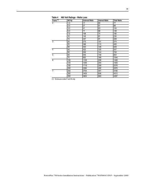
- Page 7 and 8: PowerFlex 750-Series drives generat
- Page 9: Drive Frame Catalog Number Frame 2
- Page 13 and 14: Table 7 Drive Enclosure Ratings Enc
- Page 15 and 16: Figure 2 IP20, NEMA/UL Open Type Fr
- Page 17 and 18: Figure 4 NEMA/UL Type 1 Frames 2…
- Page 19 and 20: Figure 6 IP00, NEMA/UL Open Type Fr
- Page 21 and 22: 1271.0 (50.04) 1221.0 (48.07) 881.8
- Page 23 and 24: Figure 10 IP54, NEMA/UL Type 12 Fra
- Page 25 and 26: Figure 12 IP54, NEMA/UL Type 12, Fr
- Page 27 and 28: 495.5 (19.51) 457.8 (18.02) Figure
- Page 29 and 30: 591.50 (23.287) 550.75 (21.683) 465
- Page 31 and 32: 875.0 (34.45) 812.0 (31.97) 784.0 (
- Page 33 and 34: IP00, NEMA/UL Open Type Frame 6 Lif
- Page 35 and 36: Accessing the Terminals Opening the
- Page 37 and 38: Step 3 Wire the Drive Special Consi
- Page 39 and 40: Voltage Tolerance Nominal Line Nomi
- Page 41 and 42: Terminal Block Specifications Table
- Page 43 and 44: ➎ ➍ ➌ ➊ ➋ Frame 6 Figure
- Page 45 and 46: Common Bus Power Wiring Power Termi
- Page 47 and 48: Common Bus Power Terminal Blocks Fr
- Page 49 and 50: Using 750-Series Drives with Regen
- Page 51 and 52: Table 19 400 Volt AC Input Protecti
- Page 53 and 54: Drive Power Jumper Configuration Po
- Page 55 and 56: Power Jumper Screw Removal and Stor
- Page 57 and 58: Figure 34 Frame 7 Jumper Wire Locat
- Page 59 and 60: Access Drive Control Pod 1. Remove
- Page 61 and 62:
PowerFlex 753 Main Control Board
- Page 63 and 64:
PowerFlex 755 Main Control Board
- Page 65 and 66:
Safety Enable Circuitry The drive s
- Page 67 and 68:
I/O Module 20-750-2262C-2R 20-750-2
- Page 69 and 70:
I/O Wiring Examples 51 Anlg In0 Hi
- Page 71 and 72:
Input/Output Connection Example Req
- Page 73 and 74:
Input/Output Connection Example Req
- Page 75 and 76:
Safe Torque Off Option Module 20-75
- Page 77 and 78:
Table 38 Safe Speed Monitor Paramet
- Page 79 and 80:
I/O Connection Example Encoder Sign
- Page 81 and 82:
Table 46 Dual Incremental Encoder P
- Page 83 and 84:
Table 49 Universal Feedback Increme
- Page 85 and 86:
Auxiliary Power Supply Option Modul
- Page 87 and 88:
ControlNet Option Module For comple
- Page 89 and 90:
Step 5 Start-Up Check List Prepare
- Page 91 and 92:
Navigate to Start-Up Menu Using the
- Page 93 and 94:
Soft Keys Up to five dynamic soft k
- Page 95 and 96:
Ports and Devices Drive Device Port
- Page 97 and 98:
Status Indicators PowerFlex 753 Pow
- Page 99 and 100:
Event Fault Configuration Auto No.
- Page 101 and 102:
Event Fault Configuration No. Fault
- Page 103 and 104:
Event Fault Configuration Auto No.
- Page 105 and 106:
Common Symptoms and Corrective Acti
- Page 107 and 108:
Drive (Port 0) Parameter List Numbe
- Page 109 and 110:
Number Parameter Name Group 315 SLA
- Page 111 and 112:
611 TrmPct RefA AnLo Speed Trim 612
- Page 113 and 114:
944 Drive Temp C Status 945 At Limi
- Page 115 and 116:
Notes: PowerFlex 750-Series Install