

PowerFlex 755 Install Manual.pdf
PowerFlex 755 Install Manual.pdf
PowerFlex 755 Install Manual.pdf

Create successful ePaper yourself
Turn your PDF publications into a flip-book with our unique Google optimized e-Paper software.
46<br />
➎<br />
➍<br />
➊<br />
➋<br />
Frame 6<br />
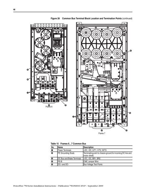
Figure 28 Common Bus Terminal Block Location and Termination Points (continued)<br />
➋<br />
Frame 7<br />
Table 15 Frames 6…7 Common Bus<br />
No. Name Description<br />
➊ Power Terminals +DC, -DC, U/T1, V/T2, W/T3<br />
➋ PE Grounding Studs Terminating point to chassis ground for incoming DC line and<br />
motor shield.<br />
➌ DC Bus and Brake Terminals +DC, -DC, BR1, BR2<br />
➍ PE-B CMC Jumper Wire<br />
➎ DC+ and DC- Bus Voltage Test Points<br />
<strong>PowerFlex</strong> 750-Series <strong>Install</strong>ation Instructions – Publication 750-IN001C-EN-P – September 2009<br />
➌<br />
➊<br />
➌<br />
➍<br />
➎


