

PowerFlex 755 Install Manual.pdf
PowerFlex 755 Install Manual.pdf
PowerFlex 755 Install Manual.pdf

Create successful ePaper yourself
Turn your PDF publications into a flip-book with our unique Google optimized e-Paper software.
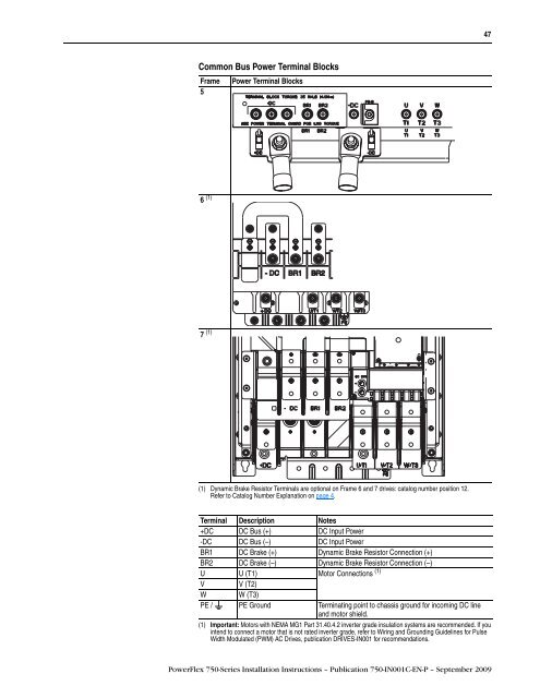
Common Bus Power Terminal Blocks<br />
Frame Power Terminal Blocks<br />
5<br />
6 (1)<br />
7 (1)<br />
(1) Dynamic Brake Resistor Terminals are optional on Frame 6 and 7 drives: catalog number position 12.<br />
Refer to Catalog Number Explanation on page 4.<br />
Terminal Description Notes<br />
+DC DC Bus (+) DC Input Power<br />
-DC DC Bus (–) DC Input Power<br />
BR1 DC Brake (+) Dynamic Brake Resistor Connection (+)<br />
BR2 DC Brake (–) Dynamic Brake Resistor Connection (–)<br />
U U (T1) Motor Connections (1)<br />
V V (T2)<br />
W W (T3)<br />
PE / PE Ground Terminating point to chassis ground for incoming DC line<br />
and motor shield.<br />
(1) Important: Motors with NEMA MG1 Part 31.40.4.2 inverter grade insulation systems are recommended. If you<br />
intend to connect a motor that is not rated inverter grade, refer to Wiring and Grounding Guidelines for Pulse<br />
Width Modulated (PWM) AC Drives, publication DRIVES-IN001 for recommendations.<br />
<strong>PowerFlex</strong> 750-Series <strong>Install</strong>ation Instructions – Publication 750-IN001C-EN-P – September 2009<br />
47


