

PowerFlex 755 Install Manual.pdf
PowerFlex 755 Install Manual.pdf
PowerFlex 755 Install Manual.pdf

You also want an ePaper? Increase the reach of your titles
YUMPU automatically turns print PDFs into web optimized ePapers that Google loves.
42<br />
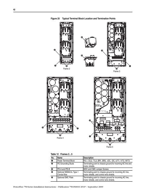
Figure 25 Typical Terminal Block Location and Termination Points<br />
➌<br />
➊ ➋<br />
➊<br />
Frame 2<br />
➋<br />
Frame 3<br />
➌ ➊<br />
➋<br />
Frame 4<br />
Table 12 Frames 2…5<br />
<strong>PowerFlex</strong> 750-Series <strong>Install</strong>ation Instructions – Publication 750-IN001C-EN-P – September 2009<br />
➍<br />
➎<br />
➌<br />
➊<br />
➌<br />
➋<br />
Frame 5<br />
No. Name Description<br />
➊ Power Terminal Block R/L1, S/L2, T/L3, BR1, BR2, +DC, -DC, U/T1, V/T2, W/T3<br />
➋ PE Grounding Studs Terminating point to chassis ground for incoming AC line and<br />
motor shields.<br />
➌ PE-A and PE-B MOV and CMC Jumper Screws<br />
➍ Optional NEMA/UL Type 1 Terminating point to chassis ground for incoming AC line,<br />
Conduit Box<br />
motor shields, and control wire shields.<br />
➎ Optional EMC Plate Terminating point to chassis ground for incoming AC line,<br />
motor shields, and control wire shields.


