- Page 1 and 2:
J-Link / J-Trace ARM User guide of
- Page 3 and 4:
Revision Date By Explanation 86 100
- Page 5 and 6:
Revision Date By Explanation 57 081
- Page 7 and 8:
Revision Date By Explanation 28 070
- Page 9 and 10:
About this document This document d
- Page 11 and 12:
11 Table of Contents 1 Introduction
- Page 13 and 14:
5.5 Multi-core debugging ..........
- Page 15 and 16:
10.2.1 Rules for series terminators
- Page 17 and 18:
Chapter 1 Introduction This chapter
- Page 19 and 20:
1.2 Supported OS J-Link/J-Trace can
- Page 21 and 22:
1.3.1 Model comparison The followin
- Page 23 and 24:
LOW level input voltage (V IL ) V I
- Page 25 and 26:
1.3.3 J-Link Ultra J-Link Ultra is
- Page 27 and 28:
• Serial Wire Viewer supported
- Page 29 and 30:
1.3.6 J-Trace ARM J-Trace is a JTAG
- Page 31 and 32:
1.3.7 J-Trace for Cortex-M3 J-Trace
- Page 33 and 34:
1.3.8 Flasher ARM Flasher ARM is a
- Page 35 and 36:
1.4 Common features of the J-Link p
- Page 37 and 38:
1.6 Supported IDEs J-Link / J-Trace
- Page 39 and 40:
Chapter 2 Licensing This chapter de
- Page 41 and 42:
2.2 Software components requiring a
- Page 43 and 44:
2.3.3 Device-based license The devi
- Page 45 and 46:
2.4 Legal use of SEGGER J-Link soft
- Page 47 and 48:
2.5.3 J-Link Pro J-Link Pro is a JT
- Page 49 and 50:
2.6 J-Link OEM versions There are s
- Page 51 and 52:
2.6.6 IAR: J-Trace IAR J-Trace is a
- Page 53 and 54:
2.8 Illegal Clones Clones are copie
- Page 55 and 56:
Chapter 3 Setup This chapter descri
- Page 57 and 58:
2. The Welcome dialog box is opened
- Page 59 and 60:
3.2 Setting up the USB interface Af
- Page 61 and 62:
3.3 Uninstalling the J-Link USB dri
- Page 63 and 64:
3.4.1.2 Connecting via Ethernet onl
- Page 65 and 66:
3.4.2.2 Configuring J-Link via web
- Page 67 and 68:
3.5.2 Using the J-Link configurator
- Page 69 and 70:
Chapter 4 J-Link and J-Trace relate
- Page 71 and 72:
4.1.2 List of additional software p
- Page 73 and 74:
4.2.2 SWO Analyzer SWO Analyzer (SW
- Page 75 and 76:
4.2.4 J-Link STM32 Commander (Comma
- Page 77 and 78:
4.2.6 J-Mem Memory Viewer J-Mem dis
- Page 79 and 80:
4.2.8 J-Link RDI (Remote Debug Inte
- Page 81 and 82:
4.3 Dedicated flash programming uti
- Page 83 and 84:
4.3.5.2 Purchasing the source code
- Page 85 and 86:
4.5 Using the J-LinkARM.dll 4.5.1 W
- Page 87 and 88:
Chapter 5 Working with J-Link and J
- Page 89 and 90:
5.2 Indicators J-Link uses indicato
- Page 91 and 92:
5.2.2 Input indicator Some newer J-
- Page 93 and 94:
SEGGER J-Flash configuration dialog
- Page 95 and 96:
5.3.3 Determining values for scan c
- Page 97 and 98:
5.4 SWD interface The J-Link suppor
- Page 99 and 100:
5.5 Multi-core debugging J-Link / J
- Page 101 and 102:
6. Choose Project|Options and confi
- Page 103 and 104:
5.6 Connecting multiple J-Links / J
- Page 105 and 106:
5.6.3 Connecting to a J-Link / J-Tr
- Page 107 and 108:
5.7.1.2 Settings In the Settings se
- Page 109 and 110:
5.7.1.3 Break/Watch In the Break/Wa
- Page 111 and 112:
5.7.1.7 SWV In this section SWV inf
- Page 113 and 114:
5.8.1.4 Type 3: No reset No reset i
- Page 115 and 116:
5.8.2.6 Type 5: Reset core & periph
- Page 117 and 118:
5.10 J-Link script files In some si
- Page 119 and 120:
Prototype __api__ int JTAG_WriteIR(
- Page 121 and 122:
Note: All global variables are trea
- Page 123 and 124:
• ARM1176JFS • CORTEX_M0 • CO
- Page 125 and 126:
5.11 Command strings The behavior o
- Page 127 and 128:
Syntax map exclude - Example This i
- Page 129 and 130:
Syntax SetCheckModeAfterRead = 0 |
- Page 131 and 132: 5.11.2 Using command strings 5.11.2
- Page 133 and 134: 5.12 Switching off CPU clock during
- Page 135 and 136: Chapter 6 Flash download and flash
- Page 137 and 138: 6.2 Licensing Some J-Links are avai
- Page 139 and 140: 6.3 Supported devices The following
- Page 141 and 142: Manufacturer Device ID Devices Free
- Page 143 and 144: Manufacturer Device ID Devices NXP*
- Page 145 and 146: Manufacturer Device ID Devices ST S
- Page 147 and 148: 6.4 Setup for different debuggers (
- Page 149 and 150: Then J-Link / J-Trace has to be sel
- Page 151 and 152: 6.5 Setup for different debuggers (
- Page 153 and 154: Chapter 7 Device specifics This cha
- Page 155 and 156: • Analog ADuC7128 • Analog ADuC
- Page 157 and 158: esults. Clearly 1. is the easiest s
- Page 159 and 160: 7.3 Freescale J-Link has been teste
- Page 161 and 162: 7.4.1 Unlocking LM3Sxxx devices If
- Page 163 and 164: If you experience problems with a p
- Page 165 and 166: 7.6 OKI J-Link has been tested with
- Page 167 and 168: If you experience problems with a p
- Page 169 and 170: 7.8 Texas Instruments J-Link has be
- Page 171 and 172: Chapter 8 Target interfaces and ada
- Page 173 and 174: Pins 4, 6, 8, 10, 12, 14, 16, 18, 2
- Page 175 and 176: PIN SIGNAL TYPE Description 15 RESE
- Page 177 and 178: 8.2 38-pin Mictor JTAG and Trace co
- Page 179 and 180: PIN SIGNAL Description 22 Trace sig
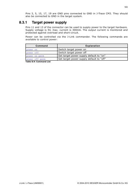
- Page 181: Parameter Min. Max. Explanation Tsh
- Page 185 and 186: Chapter 9 Background information Th
- Page 187 and 188: 9.1.4 The TAP controller The TAP co
- Page 189 and 190: 9.2 Embedded Trace Macrocell (ETM)
- Page 191 and 192: 9.2.3.2 Code coverage - Source code
- Page 193 and 194: 9.3 Embedded Trace Buffer (ETB) The
- Page 195 and 196: 9.4.4.2 JLinkArmFlash.dll - A DLL w
- Page 197 and 198: Use an application (for example JLi
- Page 199 and 200: Chapter 10 Designing the target boa
- Page 201 and 202: 10.2 Terminating the trace signal T
- Page 203 and 204: Chapter 11 Support and FAQs This ch
- Page 205 and 206: 11.2 Troubleshooting 11.2.1 General
- Page 207 and 208: 11.3 Signal analysis The following
- Page 209 and 210: 11.5 Frequently Asked Questions Sup
- Page 211 and 212: Chapter 12 Glossary This chapter de
- Page 213 and 214: ID Identifier. IEEE 1149.1 The IEEE
- Page 215 and 216: TDO The electronic signal output fr
- Page 217 and 218: Chapter 13 Literature and reference
- Page 219 and 220: A Adaptive clocking ...............