

Parallel Flash Loader Megafunction User Guide (PDF) - Altera
Parallel Flash Loader Megafunction User Guide (PDF) - Altera
Parallel Flash Loader Megafunction User Guide (PDF) - Altera

Create successful ePaper yourself
Turn your PDF publications into a flip-book with our unique Google optimized e-Paper software.
Functional Description Page 13<br />
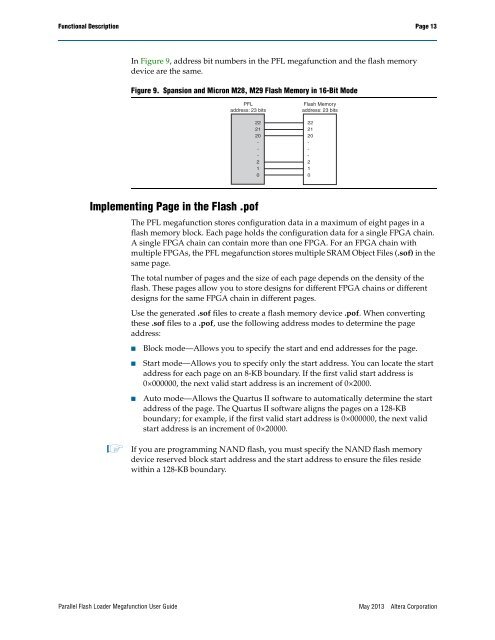
In Figure 9, address bit numbers in the PFL megafunction and the flash memory<br />
device are the same.<br />
Figure 9. Spansion and Micron M28, M29 <strong>Flash</strong> Memory in 16-Bit Mode<br />
PFL<br />
address: 23 bits<br />
22<br />
21<br />
20<br />
-<br />
-<br />
-<br />
2<br />
1<br />
0<br />
<strong>Flash</strong> Memory<br />
address: 23 bits<br />
22<br />
21<br />
20<br />
-<br />
-<br />
-<br />
2<br />
1<br />
0<br />
Implementing Page in the <strong>Flash</strong> .pof<br />
The PFL megafunction stores configuration data in a maximum of eight pages in a<br />
flash memory block. Each page holds the configuration data for a single FPGA chain.<br />
A single FPGA chain can contain more than one FPGA. For an FPGA chain with<br />
multiple FPGAs, the PFL megafunction stores multiple SRAM Object Files (.sof) in the<br />
same page.<br />
The total number of pages and the size of each page depends on the density of the<br />
flash. These pages allow you to store designs for different FPGA chains or different<br />
designs for the same FPGA chain in different pages.<br />
Use the generated .sof files to create a flash memory device .pof. When converting<br />
these .sof files to a .pof, use the following address modes to determine the page<br />
address:<br />
■<br />
■<br />
■<br />
Block mode—Allows you to specify the start and end addresses for the page.<br />
Start mode—Allows you to specify only the start address. You can locate the start<br />
address for each page on an 8-KB boundary. If the first valid start address is<br />
0×000000, the next valid start address is an increment of 0×2000.<br />
Auto mode—Allows the Quartus II software to automatically determine the start<br />
address of the page. The Quartus II software aligns the pages on a 128-KB<br />
boundary; for example, if the first valid start address is 0×000000, the next valid<br />
start address is an increment of 0×20000.<br />
1 If you are programming NAND flash, you must specify the NAND flash memory<br />
device reserved block start address and the start address to ensure the files reside<br />
within a 128-KB boundary.<br />
<strong>Parallel</strong> <strong>Flash</strong> <strong>Loader</strong> <strong>Megafunction</strong> <strong>User</strong> <strong>Guide</strong><br />
May 2013<br />
<strong>Altera</strong> Corporation


