

The System Manual of SOL-20 - History of Computers
The System Manual of SOL-20 - History of Computers
The System Manual of SOL-20 - History of Computers

Create successful ePaper yourself
Turn your PDF publications into a flip-book with our unique Google optimized e-Paper software.
PROCESSOR TECHNOLOGY CORPORATION<br />
Sol POWER SUPPLY<br />
SECTION II<br />
further from the body than the other two leads. Bend<br />
leads so that no contact is made with the heat sink<br />
when Ul is flat against the sink and its mounting hole<br />
is aligned with the holes in the sink and PC board.<br />
Apply heat sink compound per Assembly Tip 6, on page 11-5.<br />
Fasten U1 and sink to board using a 6-32 x 1/2 metal screw,<br />
lockwasher and nut. Insert screw from back (solder) side<br />
<strong>of</strong> board and drive nut finger tight.<br />
( ) Position U3 (7912) on heat sink, determine how leads<br />
must be bent as you did for U1, and bend leads. Place a<br />
rectangular mica insulator over the leads <strong>of</strong> U3 so that<br />
it fully covers the bottom side <strong>of</strong> the U3 package. Apply<br />
heat sink compound to U3, the heat sink, and both sides<br />
<strong>of</strong> the mica insulator. Bend the two outside leads <strong>of</strong> U3<br />
slightly in toward the center lead, insert leads in mountto<br />
heat sink<br />
ing holes as you did for U1, and fasten U3<br />
and PC board using a 6-32 x 1/2 Nylon screw, lockwasher and<br />
nut. Insert screw from back (solder) side <strong>of</strong> board and<br />
drive nut finger tight.<br />
( ) Position heat sink, U1 and U3 as needed to obtain correct<br />
fit and tighten the U1 and U3 mounting screws.<br />
REMEMBER, NO LEADS CAN CONTACT THE SINK. Solder all<br />
leads and trim if required.<br />
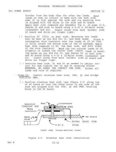
( ) Step <strong>20</strong>. Install aluminum heat sink, SCR1, Q1 and bridge<br />
rectifier EWB1.<br />
( ) Position aluminum heat sink (see Figure 2-3) along top<br />
<strong>of</strong> PC board so that the three holes in one side <strong>of</strong> the<br />
sink are aligned with the SCR1, Q1 and FWB1 mounting<br />
holes in the PC board.<br />
Heatsink<br />
Compound and<br />
Lockwasher<br />
Insulator<br />
ePC Board<br />
Solder (back) Side<br />
4-40 x 7/16 Screw<br />
(Left end, cross-section view)<br />
Figure 2-3. Aluminum heat sink installation.<br />
Rev B<br />
II-12


