

The System Manual of SOL-20 - History of Computers
The System Manual of SOL-20 - History of Computers
The System Manual of SOL-20 - History of Computers

You also want an ePaper? Increase the reach of your titles
YUMPU automatically turns print PDFs into web optimized ePapers that Google loves.
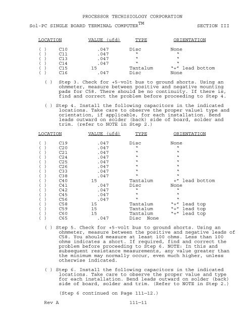
PROCESSOR TECHISIOLOGY CORPORATION<br />
Sol-PC SINGLE BOARD TERMINAL COMPUTER TM<br />
SECTION III<br />
LOCATION VALUE (ufd) TYPE ORIENTATION<br />
( ) C10 .047 Disc None<br />
( ) C11 .047 “ “<br />
( ) C13 .047 “ “<br />
( ) C14 .047 “ “<br />
( ) C15 15 Tantalum “+” lead bottom<br />
( ) C16 .047 Disc None<br />
( ) Step 3. Check for +5-volt bus to ground shorts. Using an<br />
ohmmeter, measure between positive and negative mounting<br />
pads for C58. <strong>The</strong>re should be no continuity. If there is,<br />
find and correct the problem before proceeding to Step 4.<br />
( ) Step 4. Install the following capacitors in the indicated<br />
locations. Take care to observe the proper value1 type and<br />
orientation, if applicable, for each installation. Bend<br />
leads outward on solder (back) side <strong>of</strong> board, solder and<br />
trim. (refer to NOTE in Step 2.)<br />
LOCATION VALUE (ufd) TYPE ORIENTATION<br />
( ) C19 .047 Disc None<br />
( ) C<strong>20</strong> .047 “ “<br />
( ) C21 .047 “ “<br />
( ) C24 .047 “ “<br />
( ) C25 .047 “ “<br />
( ) C26 .047 “ “<br />
( ) C33 .047 “ “<br />
( ) C38 .047 “ “<br />
( ) C40 15 Tantalum +” lead bottom<br />
( ) C41 .047 Disc None<br />
( ) C42 .047 “ “<br />
( ) C45 .047 “ “<br />
( ) C56 .047 “ “<br />
( ) C58 15 Tantalum “+” lead top<br />
( ) C59 15 Tantalum “+” lead top<br />
( ) C60 15 Tantalum “+” lead top<br />
( ) C65 .047 Disc None<br />
( ) Step 5. Check for +5-volt bus to ground shorts. Using an<br />
ohmmeter, measure between the positive and negative leads <strong>of</strong><br />
C58. You should measure at least 100 ohms. Less than 100<br />
ohms indicates a short. If required, find and correct the<br />
problem before proceeding to Step 6. NOTE: In this and<br />
subsequent resistance measurements, any value greater than<br />
the minimum may normally occur, even much higher, unless<br />
otherwise indicated.<br />
( ) Step 6. Install the following capacitors in the indicated<br />
locations. Take care to observe the proper value and type<br />
for each installation. Bend leads outward on solder (back)<br />
side <strong>of</strong> board, solder and trim. (Refer to NOTE in Step 2.)<br />
(Step 6 continued on Page 111—12.)<br />
Rev A 111—11


