

The System Manual of SOL-20 - History of Computers
The System Manual of SOL-20 - History of Computers
The System Manual of SOL-20 - History of Computers

You also want an ePaper? Increase the reach of your titles
YUMPU automatically turns print PDFs into web optimized ePapers that Google loves.
PROCESSOR TECHNOLOGY CORPORATION<br />
Sol-PC SINGLE BOARD TERMINAL COMPUTER TM<br />
SECTION III<br />
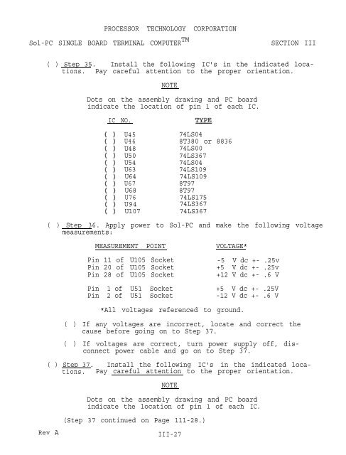
( ) Step 35. Install the following IC's in the indicated locations.<br />
Pay careful attention to the proper orientation.<br />
NOTE<br />
Dots on the assembly drawing and PC board<br />
indicate the location <strong>of</strong> pin 1 <strong>of</strong> each IC.<br />
IC NO.<br />
U45<br />
U46<br />
U48<br />
U50<br />
U54<br />
U63<br />
U64<br />
U67<br />
U68<br />
U76<br />
U94<br />
U107<br />
74LS04<br />
8T380 or 8836<br />
74LS00<br />
74LS367<br />
74LS04<br />
74LS109<br />
74LS109<br />
8T97<br />
8T97<br />
74LS175<br />
74LS367<br />
74LS367<br />
( ) Step 36. Apply power to Sol-PC and make the following voltage<br />
measurements:<br />
MEASUREMENT POINT<br />
Pin 11 <strong>of</strong> U105 Socket<br />
Pin <strong>20</strong> <strong>of</strong> U105 Socket<br />
Pin 28 <strong>of</strong> U105 Socket<br />
VOLTAGE*<br />
-5 V dc +- .25v<br />
+5 V dc +- .25v<br />
+12 V dc +- .6 V<br />
Pin 1 <strong>of</strong> U51 Socket +5 V dc +- .25V<br />
Pin 2 <strong>of</strong> U51 Socket -12 V dc +- .6 V<br />
*All voltages referenced to ground.<br />
( ) If any voltages are incorrect, locate and correct the<br />
cause before going on to Step 37.<br />
( ) If voltages are correct, turn power supply <strong>of</strong>f, disconnect<br />
power cable and go on to Step 37.<br />
( ) Step 37. Install the following IC's in the indicated locations.<br />
Pay careful attention to the proper orientation.<br />
NOTE<br />
Dots on the assembly drawing and PC board<br />
indicate the location <strong>of</strong> pin 1 <strong>of</strong> each IC.<br />
(Step 37 continued on Page 111-28.)<br />
Rev A<br />
III-27


