

The System Manual of SOL-20 - History of Computers
The System Manual of SOL-20 - History of Computers
The System Manual of SOL-20 - History of Computers

Create successful ePaper yourself
Turn your PDF publications into a flip-book with our unique Google optimized e-Paper software.
PROCESSOR TECHNOLOGY CORPORATION<br />
Sol POWER SUPPLY SECTION II<br />
Position FWB3 (MDA980-l) on power supply subchassis as shown in<br />
drawing on Page X-2. BE SURE NEGATIVE (-) TERMINAL OF<br />
FWB3 is next to transformer. Insert a 6—32 x. ½ binder or<br />
pan head screw from bottom <strong>of</strong> subchassis, place #6 lockwasher<br />
on screw and secure with 6—32 hex nut.<br />
*( ) Step 34. Connect blue transformer wires to unmarked terminals<br />
<strong>of</strong> FWB3.<br />
*( ) Step 35. Install large (2½”) mounting ring for C9 (54,000<br />
ufd capacitor) on side wall <strong>of</strong> power supply subchassis as<br />
shown in drawing on Page X-2.<br />
Position ring over the three mounting holes in the side wall<br />
<strong>of</strong> subchassis so the clamping screw faces the bottom <strong>of</strong> subchassis<br />
and so it will be accessible from the Sol—REG end <strong>of</strong><br />
the subchassis. Insert three 6—32 x ½ binder or pan head<br />
screws from outer side <strong>of</strong> side wall through the mounting<br />
holes. Place #6 lockwasher on each screw and secure with<br />
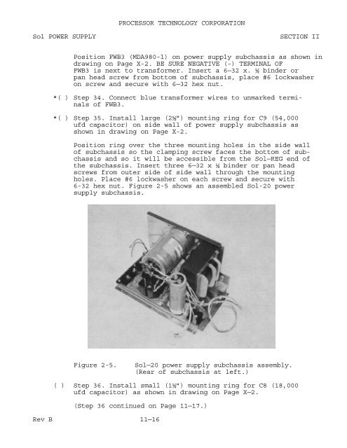
6-32 hex nut. Figure 2-5 shows an assembled Sol-<strong>20</strong> power<br />
supply subchassis.<br />
Figure 2-5.<br />
Sol—<strong>20</strong> power supply subchassis assembly.<br />
(Rear <strong>of</strong> subchassis at left.)<br />
( ) Step 36. Install small (1½”) mounting ring for C8 (18,000<br />
ufd capacitor) as shown in drawing on Page X—2.<br />
(Step 36 continued on Page 11—17.)<br />
Rev B 11—16


