

The System Manual of SOL-20 - History of Computers
The System Manual of SOL-20 - History of Computers
The System Manual of SOL-20 - History of Computers

You also want an ePaper? Increase the reach of your titles
YUMPU automatically turns print PDFs into web optimized ePapers that Google loves.
PROCESSOR TECHNOLOGY CORPORATION<br />
Sol-PC SINGLE BOARD TERMINAL COMPUTER TM<br />
SECTION III<br />
( ) Remove U75 and bend pin 5 in same manner as U42. Reinstall<br />
U75 with pin 5 out <strong>of</strong> the socket.<br />
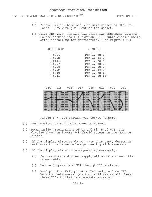
( ) Using #24 wire, install the following TEMPORARY jumpers<br />
in the sockets for U14 through U21. Double check jumpers<br />
after installing for correctness. (See Figure 3—7.)<br />
IC SOCKET<br />
JUMPER<br />
( )U14 Pin l2 to 6<br />
( )UlS Pin 12 to 5<br />
( )1J16 Pin l2 to 4<br />
( )U17 Pin 12 to 8<br />
( )U18 Pin l2 to 2<br />
( )U19 Pin 12 to 7<br />
( )U<strong>20</strong> Pin l2 to 1<br />
( )U21 Pin l2 to l6<br />
U14 U15 U16 U17 U18 U19 U<strong>20</strong> U21<br />
Figure 3-7. U14 through U21 socket jumpers.<br />
( ) Turn monitor on and apply power to Sol-PC.<br />
( ) Momentarily ground pin 1 <strong>of</strong> U2 and pin 5 <strong>of</strong> U75. <strong>The</strong><br />
display shown in Figure 3-8 should appear on the monitor<br />
screen.<br />
( ) If the display circuits do not pass this test, determine<br />
and correct the cause before proceeding with assembly.<br />
( ) If the display circuits are operating correctly:<br />
( ) Turn monitor and power supply <strong>of</strong>f and disconnect the<br />
power cable.<br />
( ) Remove jumpers from U14 through U21 sockets.<br />
( ) Bend pin 6 on U42, pin 4 on U49 and pin 5 on U75<br />
back to their normal position arid re-install these<br />
three IC’s in their appropriate sockets.<br />
111—24


