

The System Manual of SOL-20 - History of Computers
The System Manual of SOL-20 - History of Computers
The System Manual of SOL-20 - History of Computers

You also want an ePaper? Increase the reach of your titles
YUMPU automatically turns print PDFs into web optimized ePapers that Google loves.
PROCESSOR TECHNOLOGY CORPORATION<br />
Sol-PC SINGLE BOARD TERMINAL COMPUTER TM<br />
SECTION III<br />
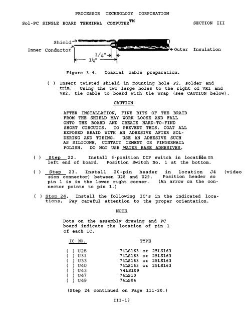
Inner Conduct0<br />
Outer Insulation<br />
Figure 3-4. Coaxial cable preparation.<br />
( ) Insert twisted shield in mounting hole P2, solder and<br />
trim. Using the two large holes to the right <strong>of</strong> VR1 and<br />
VR2, tie cable to board with tie wrap (see CAUTION below).<br />
CAUTION<br />
AFTER INSTALLATION, FINE BITS OF THE BRAID<br />
FROM THE SHIELD MAY WORK LOOSE AND FALL<br />
ONTO THE BOARD AND CREATE HARD-TO-FIND<br />
SHORT CIRCUITS. TO PREVENT THIS, COAT ALL<br />
EXPOSED BRAID WITH AN ADHESIVE AFTER <strong>SOL</strong>-<br />
DERING AND TIEING. USE AN ADHESIVE SUCH<br />
AS SILICONE, CONTACT CEMENT OR FINGERNAIL<br />
POLISH. -DO NOT - USE - WATER BASE ADHESIVES.<br />
( ) Step 22. Install 6-position DIP switch in location S1 on<br />
left end <strong>of</strong> board. Position Switch No. 1 at the bottom.<br />
( ) Step 23. Install <strong>20</strong>-pin header in location J4 (video<br />
sion connector) between U28 and U29. Position header so<br />
pin 1 is in the lower right corner. (An arrow on the connector<br />
points to pin 1.)<br />
Install the following IC's in the indicated loca-<br />
Pay careful attention to the proper orientation.<br />
NOTE<br />
Dots on the assembly drawing and PC<br />
board indicate the location <strong>of</strong> pin 1<br />
<strong>of</strong> each IC.<br />
IC NO.<br />
TYPE --<br />
74LS163 or 25LS163<br />
74LS163 or 25LS163<br />
74LS163 or 25LS163<br />
74LS163 or 25LS163<br />
74LS109<br />
74LS10<br />
74LS04<br />
(Step 24 continued on Page 111-<strong>20</strong>.)<br />
III-19


