

The System Manual of SOL-20 - History of Computers
The System Manual of SOL-20 - History of Computers
The System Manual of SOL-20 - History of Computers

Create successful ePaper yourself
Turn your PDF publications into a flip-book with our unique Google optimized e-Paper software.
PROCESSOR TECHNOLOGY CORPORATION<br />
Sol-PC SINGLE BOARD TERMINAL COMPUTERTM<br />
SECTION III<br />
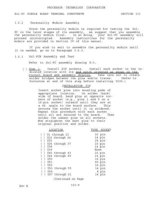
3.6.2 Personality Module Assembly<br />
Since the personality module is required for testing the Sol-<br />
PC in the later stages <strong>of</strong> its assembly, we suggest that you assemble<br />
the personality module first. In so doing, your Sol-PC assembly will<br />
proceed uninterrupted. Assembly instructions for the personality<br />
module are provided in Section IV <strong>of</strong> this manual.<br />
If you wish to wait to assemble the personality module until<br />
it is needed, go on to Paragraph 3.6.3.<br />
3.6.3<br />
Sol-PCB Assembly and Test<br />
Refer to Sol-PC assembly drawing X-3.<br />
( )<br />
Step 1. Install DIP sockets. Install each socket in the indicated<br />
location with its end notch oriented as shown on the<br />
circuit board and assembly drawinq. Take care not to create<br />
solder bridges between the pins and/or traces. (Refer to<br />
footnotes at end <strong>of</strong> this step before installing U105.)<br />
INSTALLATION TIP<br />
Insert socket pins into mounting pads <strong>of</strong><br />
appropriate location. On solder (back)<br />
side <strong>of</strong> board, bend pins at opposite corners<br />
<strong>of</strong> socket (e.g., pins 1 and 9 on a<br />
16-pin socket) outward until they are at<br />
a 45 angle to the board surface. This<br />
secures the socket until it is soldered.<br />
Repeat this procedure with each socket<br />
until all are secured to the board. <strong>The</strong>n<br />
solder the unbent pins on all sockets.<br />
Now straighten the bent pins to their<br />
original position and solder.<br />
LOCATION<br />
( ) U1 through 21<br />
( ) U22 through 24<br />
TYPE SOCKET<br />
16 pin<br />
14 pin<br />
( ) U25 24 pin<br />
( ) U26 through 37<br />
( ) U38<br />
16 pin<br />
14 pin<br />
( ) U39 None<br />
( ) U40 through 43 16 pin<br />
( ) U44 through 49 14 pin<br />
( ) U50 16 pin<br />
( ) U51<br />
40 pin<br />
( ) U52 16 pin<br />
( ) U53 through 55 14 pin<br />
( ) U56<br />
( ) U57 through 61<br />
8 pin<br />
14 pin<br />
(Continued on Page III-10.)<br />
Rev B<br />
III-9


