

Series 360, Granville-Phillips, Stabil-Ion, Ionization, Vacuum ...
Series 360, Granville-Phillips, Stabil-Ion, Ionization, Vacuum ...
Series 360, Granville-Phillips, Stabil-Ion, Ionization, Vacuum ...

You also want an ePaper? Increase the reach of your titles
YUMPU automatically turns print PDFs into web optimized ePapers that Google loves.
2 Initial Setup Procedures<br />
2.1.1 Top Cover Removal<br />
1. With power off, remove any<br />
cables from Control Unit rear<br />
panel.<br />
2. Observe antistatic precautions<br />
to avoid damaging static<br />
sensitive components inside<br />
the chassis. Use a grounded,<br />
conductive work surface. Do<br />
not handle integrated circuits<br />
(IC) devices more than<br />
necessary, and only when<br />
wearing a high impedance<br />
ground strap.<br />
(A high impedance helps<br />
protect human life in case of<br />
inadvertent contact with high<br />
voltage.)<br />
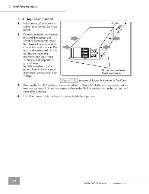
Figure 2-3<br />
3. Remove the four <strong>Phillips</strong> head screws identified in Figure 2-3. If the unit is equipped with a<br />
rear bracket instead of one rear screw, unfasten the <strong>Phillips</strong> head screw on the bracket, and<br />
slide off the bracket.<br />
4. Lift off top cover. Note the layout drawing inside the top cover.<br />
1<br />
2<br />
3<br />
4<br />
5<br />
6<br />
O<br />
O<br />
O<br />
O<br />
Bracket<br />
Do not remove the two<br />
lower front screws<br />
Location of Screws for Removal of Top Cover.<br />
2-2<br />
<strong>Series</strong> <strong>360</strong> <strong>Stabil</strong>-<strong>Ion</strong> December, 2001


