

Direct Power and Torque Control of AC/DC/AC Converter-Fed ...
Direct Power and Torque Control of AC/DC/AC Converter-Fed ...
Direct Power and Torque Control of AC/DC/AC Converter-Fed ...

You also want an ePaper? Increase the reach of your titles
YUMPU automatically turns print PDFs into web optimized ePapers that Google loves.
6. Simulation <strong>and</strong> Experimental Results<br />
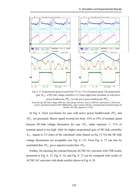
Fig. 6. 17. Experimental speed reversal from 71% to -71% <strong>of</strong> nominal speed. The proportional<br />
gain K<br />
PU<br />
<strong>of</strong> <strong>DC</strong>-link voltage controller is 3.5 times higher then calculated; a) with active<br />
power feedforward PF , b) with active power feedforward<br />
PF<br />
UI<br />
.<br />
Ω<br />
From the top: <strong>DC</strong>-link voltage 100V/div, line current 10A/div, active 2.5kW/div <strong>and</strong> reactive 2.5kVar/div<br />
power, mechanical speed <strong>of</strong> IM 1000rpm/div, stator current 10A/div, comm<strong>and</strong> <strong>and</strong> estimated torque 20<br />
Nm/div. <strong>DC</strong>-link capacitor C=47uF<br />
In Fig. 6. 16a,b waveforms for case with active power feedforwards<br />
PF<br />
Ω <strong>and</strong><br />
PF<br />
UI<br />
are presented. Shown speed reversal are from -53% to 53% <strong>of</strong> nominal speed<br />
because <strong>DC</strong>-link voltage fluctuation for case PF<br />
Ω<br />
under transient +/- 71% <strong>of</strong><br />
nominal speed is too high. Only for higher proportional gain <strong>of</strong> <strong>DC</strong>-link controller<br />
K<br />
PU<br />
equals to 3.5 times <strong>of</strong> the calculated value (based on Eq. (3.73)) the <strong>DC</strong>-link<br />
voltage fluctuations are acceptable (see Fig. 6. 17). From Fig. 6. 17 can also be<br />
concluded that<br />
PF<br />
UI<br />
gives superior results then PF<br />
Ω .<br />
Further, for stressing the contrast between <strong>AC</strong>/<strong>DC</strong>/<strong>AC</strong> converter with VSR results<br />
presented in Fig. 6. 15, Fig. 6. 16, <strong>and</strong> Fig. 6. 17 can be compared with results <strong>of</strong><br />
<strong>AC</strong>/<strong>DC</strong>/<strong>AC</strong> converter with diode rectifier shown in Fig. 6. 18.<br />
120


![[TCP] Opis układu - Instytut Sterowania i Elektroniki Przemysłowej ...](https://img.yumpu.com/23535443/1/184x260/tcp-opis-ukladu-instytut-sterowania-i-elektroniki-przemyslowej-.jpg?quality=85)
