

Direct Power and Torque Control of AC/DC/AC Converter-Fed ...
Direct Power and Torque Control of AC/DC/AC Converter-Fed ...
Direct Power and Torque Control of AC/DC/AC Converter-Fed ...

You also want an ePaper? Increase the reach of your titles
YUMPU automatically turns print PDFs into web optimized ePapers that Google loves.
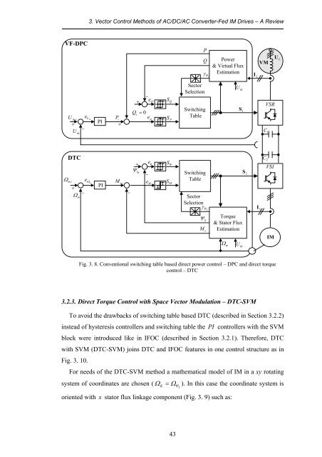
3. Vector <strong>Control</strong> Methods <strong>of</strong> <strong>AC</strong>/<strong>DC</strong>/<strong>AC</strong> <strong>Converter</strong>-<strong>Fed</strong> IM Drives – A Review<br />
VF-DPC<br />
P<br />
Q<br />
γ ΨL<br />
<strong>Power</strong><br />
& Virtual Flux<br />
Estimation<br />
I L<br />
VM<br />
U L<br />
Ω mc<br />
U dcc<br />
+<br />
U dc<br />
DTC<br />
+<br />
Ω m<br />
−<br />
−<br />
e U<br />
dc<br />
e Ω m<br />
PI<br />
PI<br />
P c<br />
+<br />
M ec<br />
−<br />
Q c<br />
+<br />
+<br />
Ψ Sc<br />
= 0<br />
−<br />
e p<br />
e ψ<br />
−<br />
e Q<br />
e M<br />
S Q<br />
S P<br />
S Ψ<br />
S M<br />
Sector<br />
Selection<br />
Switching<br />
Table<br />
Switching<br />
Table<br />
Sector<br />
Selection<br />
U dc<br />
S 1<br />
S 2<br />
VSR<br />
C 1<br />
C 2<br />
VSI<br />
γ ΨS<br />
I S<br />
Ψ S<br />
M e<br />
<strong>Torque</strong><br />
& Stator Flux<br />
Estimation<br />
Ωm<br />
U<br />
dc<br />
IM<br />
Fig. 3. 8. Conventional switching table based direct power control – DPC <strong>and</strong> direct torque<br />
control – DTC<br />
3.2.3. <strong>Direct</strong> <strong>Torque</strong> <strong>Control</strong> with Space Vector Modulation – DTC-SVM<br />
To avoid the drawbacks <strong>of</strong> switching table based DTC (described in Section 3.2.2)<br />
instead <strong>of</strong> hysteresis controllers <strong>and</strong> switching table the PI controllers with the SVM<br />
block were introduced like in IFOC (described in Section 3.2.1). Therefore, DTC<br />
with SVM (DTC-SVM) joins DTC <strong>and</strong> IFOC features in one control structure as in<br />
Fig. 3. 10.<br />
For needs <strong>of</strong> the DTC-SVM method a mathematical model <strong>of</strong> IM in a xy rotating<br />
system <strong>of</strong> coordinates are chosen ( Ω = Ω ). In this case the coordinate system is<br />
oriented with x stator flux linkage component (Fig. 3. 9) such as:<br />
K<br />
Ψ<br />
S<br />
43


![[TCP] Opis układu - Instytut Sterowania i Elektroniki Przemysłowej ...](https://img.yumpu.com/23535443/1/184x260/tcp-opis-ukladu-instytut-sterowania-i-elektroniki-przemyslowej-.jpg?quality=85)
