

Direct Power and Torque Control of AC/DC/AC Converter-Fed ...
Direct Power and Torque Control of AC/DC/AC Converter-Fed ...
Direct Power and Torque Control of AC/DC/AC Converter-Fed ...

You also want an ePaper? Increase the reach of your titles
YUMPU automatically turns print PDFs into web optimized ePapers that Google loves.
3. Vector <strong>Control</strong> Methods <strong>of</strong> <strong>AC</strong>/<strong>DC</strong>/<strong>AC</strong> <strong>Converter</strong>-<strong>Fed</strong> IM Drives – A Review<br />
U px<br />
U Lx<br />
= 0<br />
− + 1 ILx<br />
sL + R<br />
U py<br />
−<br />
+<br />
U<br />
Ly<br />
= U Lm<br />
1<br />
sL + R<br />
I<br />
Ly<br />
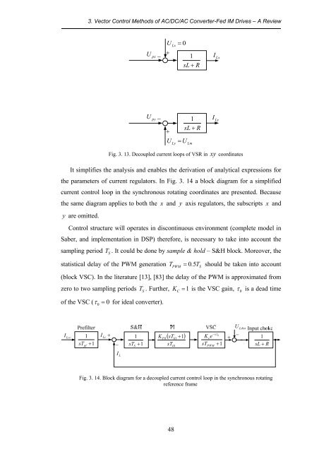
Fig. 3. 13. Decoupled current loops <strong>of</strong> VSR in xy coordinates<br />
It simplifies the analysis <strong>and</strong> enables the derivation <strong>of</strong> analytical expressions for<br />
the parameters <strong>of</strong> current regulators. In Fig. 3. 14 a block diagram for a simplified<br />
current control loop in the synchronous rotating coordinates are presented. Because<br />
the same diagram applies to both the x <strong>and</strong> y axis regulators, the subscripts x <strong>and</strong><br />
y are omitted.<br />
<strong>Control</strong> structure will operates in discontinuous environment (complete model in<br />
Saber, <strong>and</strong> implementation in DSP) therefore, is necessary to take into account the<br />
sampling period T<br />
S<br />
. It could be done by sample & hold – S&H block. Moreover, the<br />
statistical delay <strong>of</strong> the PWM generation<br />
T = 0.<br />
5T<br />
should be taken into account<br />
PWM<br />
S<br />
(block VSC). In the literature [13], [83] the delay <strong>of</strong> the PWM is approximated from<br />
zero to two sampling periods T<br />
S<br />
. Further, K<br />
C<br />
= 1 is the VSC gain, τ<br />
0<br />
is a dead time<br />
<strong>of</strong> the VSC ( τ<br />
0<br />
= 0 for ideal converter).<br />
I Lcc<br />
sT pf<br />
1<br />
+ 1<br />
I<br />
Lc<br />
+<br />
−<br />
1<br />
sT S<br />
+ 1<br />
( sT )<br />
K +<br />
sT<br />
Pi1 Ii1<br />
1<br />
Ii1<br />
K e<br />
sT<br />
−sτ<br />
0<br />
c<br />
PWM<br />
+ 1<br />
+<br />
U Ldist<br />
−<br />
1<br />
sL + R<br />
I L<br />
Fig. 3. 14. Block diagram for a decoupled current control loop in the synchronous rotating<br />
reference frame<br />
48


![[TCP] Opis układu - Instytut Sterowania i Elektroniki Przemysłowej ...](https://img.yumpu.com/23535443/1/184x260/tcp-opis-ukladu-instytut-sterowania-i-elektroniki-przemyslowej-.jpg?quality=85)
