Direct Power and Torque Control of AC/DC/AC Converter-Fed ...
Direct Power and Torque Control of AC/DC/AC Converter-Fed ...
Direct Power and Torque Control of AC/DC/AC Converter-Fed ...
Create successful ePaper yourself
Turn your PDF publications into a flip-book with our unique Google optimized e-Paper software.
3. Vector <strong>Control</strong> Methods <strong>of</strong> <strong>AC</strong>/<strong>DC</strong>/<strong>AC</strong> <strong>Converter</strong>-<strong>Fed</strong> IM Drives – A Review<br />
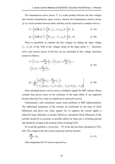
The instantaneous active power P is a scalar product between the line voltages<br />
<strong>and</strong> currents instantaneous space vectors, whereas the instantaneous reactive power<br />
Q is a vector product between them, <strong>and</strong> they can be expressed in complex form as:<br />
3<br />
P =<br />
2<br />
Re<br />
* 3<br />
3<br />
{ ULIL<br />
} = ( U<br />
L<br />
IL<br />
+ U<br />
L<br />
IL<br />
) = UL<br />
⋅I<br />
L<br />
2<br />
α α β β<br />
(3. 43)<br />
2<br />
* 3<br />
3<br />
{ U<br />
LIL<br />
} = ( U<br />
L<br />
I<br />
L<br />
−U<br />
L<br />
I<br />
L<br />
) = UL<br />
× IL<br />
3<br />
Q = Im<br />
β α α β<br />
(3. 44)<br />
2<br />
2<br />
2<br />
There is possibility to estimate the line voltages by adding the input voltage<br />
U<br />
p<br />
= U dc<br />
S 1<br />
<strong>of</strong> the VSR to the voltages drops on the input choke U<br />
I<br />
. Therefore,<br />
active <strong>and</strong> reactive power <strong>of</strong> the line can be calculated in line voltage sensorless<br />
manner as follows:<br />
⎛<br />
P = ⎜U<br />
⎝<br />
⎛<br />
+ ⎜U<br />
⎝<br />
dc<br />
S<br />
dc<br />
C<br />
S<br />
A<br />
dI<br />
+ L<br />
dt<br />
dI<br />
+ L<br />
dt<br />
LC<br />
LA<br />
⎞<br />
⎟I<br />
⎠<br />
⎞<br />
⎟I<br />
⎠<br />
LC<br />
LA<br />
⎛<br />
+ ⎜U<br />
⎝<br />
dc<br />
S<br />
B<br />
dI<br />
+ L<br />
dt<br />
LB<br />
⎞<br />
⎟I<br />
⎠<br />
LB<br />
+<br />
(3. 45)<br />
Q =<br />
⎧ ⎛ dI<br />
1 ⎪3L⎜<br />
⎨ ⎝ dt<br />
3 ⎪<br />
⎩−U<br />
dc<br />
LA<br />
I<br />
LC<br />
dI<br />
−<br />
dt<br />
LC<br />
I<br />
LA<br />
⎞<br />
⎟ +<br />
⎠<br />
[ S ( − ) + ( − ) + ( − )] ⎪ A<br />
ILB<br />
I<br />
LC<br />
SB<br />
I<br />
LC<br />
I<br />
LA<br />
SC<br />
ILA<br />
I<br />
LB ⎭<br />
⎫<br />
⎪<br />
⎬<br />
(3. 46)<br />
Such calculated power can be used as a feedback signals for DPC scheme. Please<br />
consider that, power losses on the resistance <strong>of</strong> the input choke R are neglected<br />
because they have low value in comparison to total active power.<br />
Unfortunately, such calculation causes some problems in DSP implementation.<br />
The differential operations <strong>of</strong> the currents are performed on the basis <strong>of</strong> finite<br />
differences <strong>and</strong> gives very noisy signals. So, to suppress the current ripples a<br />
relatively large inductance is needed. Moreover, calculation finite differences <strong>of</strong> the<br />
currents should be as accurate as possible (about ten times per a switching period)<br />
<strong>and</strong> should be avoided at the moment <strong>of</strong> the switching [105].<br />
To avoid this problem a virtual flux – VF <strong>of</strong> the line has been introduced in [93],<br />
[95]. The voltage in the line can be expressed with the formula:<br />
Ψ<br />
L = UL<br />
(3. 47)<br />
d<br />
dt<br />
After integration the VF can be expressed as:<br />
55


![[TCP] Opis układu - Instytut Sterowania i Elektroniki Przemysłowej ...](https://img.yumpu.com/23535443/1/184x260/tcp-opis-ukladu-instytut-sterowania-i-elektroniki-przemyslowej-.jpg?quality=85)
